Carter®
Pressure Refueling Nozzle
Model 64348
Design Concepts
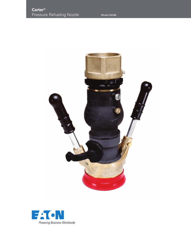
Eaton’s Carter Model 64348
underwing fueling nozzle has
been used worldwide in the
aircraft fueling industry for many
years. It includes a true swivel
disconnect and compact flow
control handle, allowing easy
connection to the aircraft.
•
Flow control handle of high
strength zinc-aluminum alloy
•
Replaceable bicycle handles and grips standard for
ease of operation. Circular
grip optional.
•
Two threaded ports in
nozzle body for simultaneous vacuum breaker and
product sampling fitting
installation are standard
•
Lightweight and rugged
•
Modular construction with
use of bolt flanges minimized
•
2, 2½, and 3-inch NPT and
BSPP threaded QD inlets
available
•
Optional 40, 60 and 100-mesh
screens retained with snap
rings for ease of removal
•
35 psi (2.413 bar), 45 psi
(3.103 bar) & 55 psi (3.792)
hose end control valves
(HECV) available
•
Dry break or ball valve for
easy strainer inspection
available
Features
•
Easier swiveling under
all conditions. Swivel
independent of quick
disconnect (QD)
•
Connects to 3-lug
international standard
aircraft adapter
•
Designed in accordance
with new SAE design
specification for commercial
nozzles AS5877
•
•
Self-adjusting pressureloaded nose seal. No
mechanical adjustments
or springs used. Leak free
under extreme side loads,
worn adapters and extreme
temperatures.
Optional easy change nose
seal — no tools required
•
Lead-in ramps (interface
with aircraft adapter lugs) of
stainless steel for longer life
•
Positive mechanical interlock — nozzle cannot be
opened until connected
to aircraft and cannot be
removed from aircraft in the
open position
•
Low pressure drop
•
Optional bonding cable and
vacuum breaker
•
Redundant safety lock
on QD
Envelope Dimensions
Dimensions shown in inches (millimeters)
Options
Dimension “A”
in
(mm)
3H, K-N, P
6H, K-N, P
7H, K-N, P
9H, K-N, P
J
F*3H, K-N, P
F*26H, K-N, P, F*6H, K-N, P
F*17H, K-N, P, F*7H, K-N, P
F*F*3H, K-N, P,
F*F*26H, K-N, P, F*6H, K-N, P
F*F*29K, N, P, F*F*9K, N, P
F*F29L, M, F*F9L, M
14.51
9.46
11.72
9.59
8.20
18.06
14.65
16.41
2.71
19.84
19.9
20.49
* 3, 4 or 5 HECV
2
EATON Aerospace Group
TF100-106D
May 2013
(368.55)
(240.28)
(297.69)
(243.59)
(208.28)
(146.50)
(372.11)
(416.81)
(68.83)
(503.94)
(505.46)
(520.45)
Technical Data
The Hose End Control Valve
(HECV) is designed to limit
pressure at its outlet (at the
pressure sensing port in the
nozzle). The control pressure is a
function of the main spring that
loads the poppet. In addition,
surge and lockup (no flow
pressure) are controlled. Refer to
Model 60129-1 brochure (TF10076) for more details on how this
is accomplished.
The curves described below are
typical for the inlet pressures and
flow rates shown in a system with
appropriate back pressure. These
curves are applicable to all Eaton
Carter HECV models.
The following characteristics
are typical:
Curve 3 Control pressure with 75 psi
(5.171 bar) inlet pressure
•
•
•
Curve 2 Control pressure with 90 psi
(6.205 bar) inlet pressure
Pressure limitation — 5 psi
(0.345 bar) over spring
setting with inlet pressure
up to 100 psi (6.895 bar)
•
Hysteresis (difference in
pressure limits between
increasing and decreasing
flow rates) — pressure limits
with decreasing flow rates
will normally be slightly
greater than for increasing
flow rates
•
Defueling is possible
through unit; however, a
blockout device is required
to maintain maximum flow.
Use Carter brand Model
61656 blockout device.
•
Model 61656 blockout device
is recommended if system
secondary control valve is to
be checked
40
(2.758)
1
2
3
30
(2.068)
20
(1.379)
100
(378)
200
(757)
300
(1,135)
400
(1,514)
500
(1,892)
600
(2,271)
Flow Rate - USgpm (l/min)
60
(4.137)
45 psi HECV
50
(3.448)
1
40
(2.758)
2
3
30
(2.068)
20
(1.379)
100
(378)
200
(757)
300
(1,135)
400
(1,514)
500
(1,892)
600
(2,271)
Flow Rate - USgpm (l/min)
60
(4.137)
55 psi HECV
50
(3.448)
Surge pressure control —
65 psi (5.171 bar) maximum
for 55 psi (3.792 bar) HECV.
55 psi (3.792 bar) maximum
for 35 psi (2.413 bar) and
45 psi (3.103 bar) HECVs.
All HECV spring settings
have 0.5 second valve
closure (minimum).
•
35 psi HECV
50
(3.448)
Curve 1 Control pressure with 100 psi
(6.895 bar) inlet pressure
Normal spring setting
(maximum pressure limits
will be 5 psi (0.345 bar)
greater than spring). Spring
settings of 35 psi (2.413 bar),
45 psi (3.103 bar) and 55 psi
(3.792 bar) available.
Lock up pressure — 10 psi
(0.689 bar) maximum over
spring setting for 45 psi
(3.103 bar) and 55 psi (3.792
bar) units. Maximum of 20 psi
(1.379 bar) over spring setting
for 35 psi (2.413 bar) unit.
60
(4.137)
HECV Pressure Drop Curves
Outlet Pressure - psi (bar)
Hose End Control Valves
1
2
3
40
(2.758)
30
(2.068)
20
(1.379)
100
(378)
200
(757)
300
(1,135)
400
(1,514)
500
(1,892)
600
(2,271)
Flow Rate - USgpm (l/min)
Flow Characteristics
Model 64348 flow rates, including
aircraft adapter use
Curve 1 64348C6H nozzle with 100mesh screen and 2½-inch inlet
Curve 2 643486H nozzle without screen
and with 2-½ inch inlet
Curve 3 64348CF46H nozzle with 100mesh screen, 45 psi (3.103 bar)
HECV and 2½-inch inlet
EATON Aerospace Group
TF100-106D
May 2013
3
Ordering Data
Part 1 - Model number
64348
The part number for a complete
nozzle consists of four parts as
illustrated (right) and described
below.
Part 4 - Letter describing the inlet thread type and size
Part 3 - Number and/or letter describing the various adapters, ball valves
and other accessories as noted below
Part 2 - Option letters describing various changes to basic nozzle
Part 2
The following options may be added
as Part 2 of the part number as
indicated above to order a unit to
meet your requirement.
Part 3
The configuration of the inlet is
defined by adding the appropriate
number or number and option letter
from the table (right) in conjunction
with the appropriate option letter
from Part 4 below. The nozzle may
terminate in an adapter half only, if
desired. In this case, leave Part 4
blank. To obtain a female half, QD
or dry break, or to complete the
specification of the ball valve outlet,
Part 4 must be completed.
Option
Description
Option
Description
*A
Adds 40-mesh screen
G
Replaces standard handles with long handles
*B
Adds 60-mesh screen
H
*C
D
E
**F3
**F4
Adds 100-mesh screen
Adds bonding cable
Adds vacuum breaker
Adds 35 psi (2.413 bar) HECV
Adds 45 psi (3.103 bar) HECV
J
Q
***R
T
U
Adds drag ring to nozzle with any Option F in
conjunction with option T or Options 1 or 6
from Part 3
Adds adapter to allow mating to 60427 QD
Adds fuel sample QD (GTP-235-3/8)
Adds flight refueling adapter
Adds adapter to mate with Whittaker accessories
Replaces standard handle with circular handle
**F5
*
Adds 55 psi (3.792 bar) HECV
Options A, B and C only available when a male half from Part 3 or Option R is specified
**
To obtain a nozzle with a dual HECV setup, specify two options in series, e.g. F5F4 results in 55 psi (3.792 bar) and 45 psi
(3.103 bar) units with the former assembled nearest the nozzle inlet. If two HECVs are desired specify the highest pressure
setting first.
***
Option R only available with 47013 HECV
Option
Description
Option
Description
*1
*2
For nozzle with flanged inlet HECV
For nozzle with swivel inlet HECV
R
4
3
6
D
Adds ball valve (64015). Part 4 must be completed
with option 3. Add options D, E, J and R for other
accessories to complete the specification.
Adds glass inspection port to ball valve
Adds defuel key with Option 3 only
Adds male adapter half (44697) to mate with basic
nozzle and dry break QD (61154)
Adds male adapter half to mate standard QD
E
Adds drag ring to ball valve
9
J
Adds operating handle with Option 3 only
7
Adds male adapter half to mate dry break QD when a
single HECV is used
Adds male adapter half (43046 with HECV, 44362
without HECV) to mate 60427 style QD
* If Option 1 or 2 is not used with any other option, then the shortest configuration nozzle will be provided
Part 4
Options specifying the desired thread
for adapters or ball valves selected in
Part 3.
Option
Description
Option
Description
H
Inlet thread — 2½-inch NPT
M
K
L
Inlet thread — 2½-inch BSPP
Inlet thread — 3 inch NPT
P
Inlet thread — 3-inch BSPP
(not available with Option 3 ball valves)
Inlet thread — 2-inch NPT
Examples:
64348CD6H
Nozzle with 100-mesh screen, bonding cable and standard QD with 2-½ inch NPT inlet thread
64348BF41
Nozzle with 60-mesh screen, 45 psi (3.103 bar) HECV with inlet flange to mate 60427 type accessories.
Note — no inlet QD or other configuration is specified in this case.
64348F514P Nozzle with 55 psi (3.792 bar) HECV with flanged adapter half and 61154 dry break with 2 inch NPT inlet.
Note — swivel adapter half can be specified by using 64348F524P.
4
EATON Aerospace Group
TF100-106D
May 2013
Illustrated Options & Weights
* For a dual HECV setup specify
two options in series; e.g. F5F4
results in 55 psi (3.792 bar) and 45
psi (3.103 bar) units with the former
assembled nearest the nozzle inlet.
If two HECVs are desired, specify
the highest pressure setting first.
The following special tools
are recommended for the
maintenance of the Model
64348 nozzle:
61607 Ball Tool for
Model 64348/64349/61428 &
61429 Nozzles
Model 61607 ball removal and
installation tool is utilized to
collect and automatically count
the balls used in the swivel
joints of the nozzle. It is simple
to use and assures that the
proper installation is achieved.
It is suggested that a separate
tool be used for each swivel joint.
A minimum of two are required
for the simplest of nozzle
configurations (one for the collar
swivel and one for the hose
swivel). Three are required for a
nozzle having a hose end control
valve (HECV) or a ball valve.
64000 Poppet Adjustment
Gauge
This simple inexpensive gauge
provides an accurate method of
achieving the proper adjustment
of the poppet of Model 64348
nozzle. The gauge can be
used on all Eaton underwing
nozzles, except Models 64200
and 64250. Use gauge Model
64250ST-1 for these later
models.
EATON Aerospace Group
61656 Blockout Device
Model 61656 Blockout Device
is recommended for use when
defueling through a hose end
control valve (HECV) or when
it is necessary to check a
secondary pressure control
device in a system. Model 61656
does not introduce fuel into the
ambient port of the HECV which
can later become a dangerous
spray during operation. It can be
used on most Eaton hose end
control valves.
TF100-106D
May 2013
5
Eaton
Aerospace Group
Fluid & Electrical Distribution Division
9650 Jeronimo Road
Irvine, California 92618
Phone: (949) 452 9500
Fax: (949) 452 9992
E-mail: groundfueling@eaton.com
Eaton
Aerospace Group
9650 Jeronimo Road
Irvine, California 92618
Phone: (949) 452 9500
Fax: (949) 452 9555
www.eaton.com/aerospace
Copyright © 2013 Eaton
All Rights Reserved
Form No. TF100-106D
May 2013


