Insert type Hose burst
advertisement

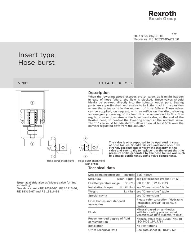
1/2 RE 18329-85/03.16 Replaces: RE 18329-85/02.16 Insert type Hose burst VPN1 0T.F4.01 - X - Y - Z Description When the lowering speed exceeds preset value, as it might happen in case of hose failure, the flow is blocked. These valves should ideally be screwed directly into the actuator outlet port. Sealing parts are superfinished and enable to lock the load in the position where the actuator is in the moment of hose failure. These valves can be supplied, on request, with an orifice on the disc, allowing an emergency lowering of the load. It is recommended to fit a flow regulator valve downstream the hose burst valve, at the end of the flexible hose, to control the lowering speed at the nominal value. The “R” gap must be adjusted to allow a flow at least 50% over the nominal regulated flow from the actuator. The valve is only supposed to be operated in case of hose failure. Should this circumstance occur, we strongly recommend to verify the integrity of the valve and eventually to replace it in the event that the pressure spike generated by the hose failure was such to damage permanently some valve components. Hose burst check valve Hose burst check valve with orifice Technical data Max. operating pressure Max. flow Note: available also as“Sleeve valve for line mounting” See data sheets RE 18316-85, RE 18316-86, RE 18316-87 and RE 18316-88 bar (psi) 315 (4500) l/min. (gpm) see performance graphs (‘R‘-Q) Fluid temperature range Installation torque Weight °C (°F) -30 to 100 (-22 to 212) Nm (ft-lbs) see “Dimensions” table kg (lbs) see “Dimensions” table Special cavity Lines bodies and standard assemblies Fluids see “Dimensions” Please refer to section “Hydraulic integrated circuit” or consult factory Mineral-based or synthetics with lubricating properties at viscosities of 10 to 500 mm2/s (cSt) Recommended degree of fluid contamination Nominal value max. 10µm (NAS 8) ISO 4406 19/17/14 Installation No restrictions Other Technical Data See data sheet RE 18350-50 2/2 0TF401XYZ Bosch Rexroth Oil Control S.p.A. RE 18329-85/03.16 Dimensions G* A B C D E G 1/4 8.5 (0.34) 17.5 (0.69) 8 (0.32) 9.5 (0.37) 2.4 (0.1) G 3/8 10.5 (0.41) 23 (0.91) 10.5 (0.41) G 1/2 13 (0.51) 25 (0.98) G 3/4 16 (0.63) 30.5 (1.2) F H Weight Inst. torque kg (lbs) Nm (ft-lbs) Hex min. max. 2 (1.5) 4 (1) 25 (7) 0.010 (0.022) 3 (2) 6 (2) 50 (13) 7 (0.28) 0.020 (0.044) 4 (3) 16 (4) 80 (21) 7 (0.28) 0.042 (0.093) 10 (7) 25 (7) 150 (40) 11 on request (0.43) 5.5 (0.22) 0.005 (0.011) 12.5 (0.49) 3.5 11 on request (0.14) (0.43) 5.5 (0.22) 12 (0.47) 15 (0.59) 4.5 15 on request (0.18) (0.59) 17 (0.67) 18 (0.71) 6 16 on request (0.24) (0.63) * Thread in accordance with ISO 228-1 Flow max. l/min. (gpm) Note: Metric versions available on request. Consult factory. Fitting tool dimensions Type F L L1 L2 Tool code Material number VPN1.G14 11.3 120 110 60 (0.45) (4.72) (4.33) (2.36) AVA18 R931002467 VPN1.G38 15 120 108 80 (0.59) (4.72) (4.25) (3.15) AVA18-01 R931002468 VPN1.G12 18.8 120 108 80 (0.74) (4.72) (4.25) (3.15) AVA18-02 R931002469 VPN1.G34 24 120 108 80 (0.95) (4.72) (4.25) (3.15) AVA18-03 R931002470 Bosch Rexroth Oil Control S.p.A. RE 18329-85/03.16 0TF401XYZ 3/4 Performance Performance curves R/flow (allowance can be ±10% from the curve) After assembling the valve are preadjustated at the following values 0.5 mm (0.02 in) for G 1/4 and G 3/8 0.7 mm (0.03 in) for G 1/2 and G 3/4 Flow performance from ‘1‘ to ‘2‘ depending on R-lenght G 1/4 G 1/2 G 3/8 G 3/4 Special flow settings available. Please contact factory authorized representative for ordering code 4/2 0TF401XYZ Bosch Rexroth Oil Control S.p.A. RE 18329-85/03.16 Ordering code 0T.F4.01 X Y Z * Series 0/A to L unchanged performances and dimensions Insert type Check, hose burst Adjustments - = 03 Locking nut + counter nut see graphs ( ‘R‘ - Q ) Port sizes = 09 G 1/4 = 02 G 3/8 = 03 G 1/2 = 04 G 3/4 = = = = = = = = = = = = 00 01 02 03 04 05 06 07 08 09 10 11 Orifice diameter (mm) no orifice 0.5 0.6 0.7 0.8 0.9 1 1.2 1.3 1.5 1.9 2 Note: Metric versions available on request. Consult factory. Type Material number 0TF401030200000 R931000017 0TF401030300000 R901127828 0TF401030400000 R901161819 0TF401030900000 R931000021 Bosch Rexroth Oil Control S.p.A. Via Leonardo da Vinci 5 P.O. Box no. 5 41015 Nonantola – Modena, Italy Tel. +39 059 887 611 Fax +39 059 547 848 compact-hydraulics-cv@boschrexroth.com www.boschrexroth.com/compacthydraulics Type Material number © This document, as well as the data, specifications and other information set forth in it, are the exclusive property of Bosch Rexroth Oil Control S.p.a.. It may not be reproduced or given to third parties without its consent. The data specified above only serve to describe the product. No statements concerning a certain condition or suitability for a certain application can be derived from our information. The information given does not release the user from the obligation of own judgment and verification. It must be remembered that our products are subject to a natural process of wear and aging. Subject to change.


