Evaluation of SAW-type Vibration Sensor using LTGA Crystal LTGA
advertisement

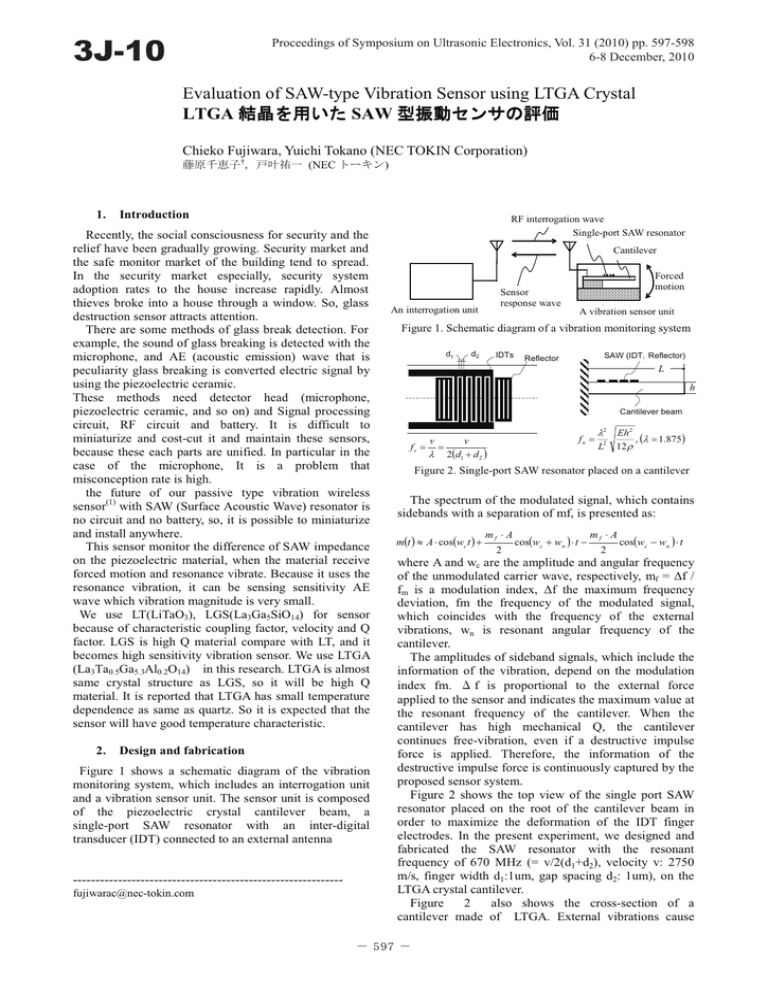
3J-10 Proceedings of Symposium on Ultrasonic Electronics, Vol. 31 (2010) pp. 597-598 6-8 December, 2010 Evaluation of SAW-type Vibration Sensor using LTGA Crystal LTGA ⚿᥏ࠍ ⚿᥏ࠍ↪ߚ SAW ဳᝄേࡦࠨ ဳᝄേࡦࠨߩ ࡦࠨߩ⹏ଔ Chieko Fujiwara, Yuichi Tokano (NEC TOKIN Corporation) ⮮ේජᕺሶ†㧘ᚭฟ৻ (NEC ࠻ࠠࡦ) 1. Introduction Recently, the social consciousness for security and the relief have been gradually growing. Security market and the safe monitor market of the building tend to spread. In the security market especially, security system adoption rates to the house increase rapidly. Almost thieves broke into a house through a window. So, glass destruction sensor attracts attention. There are some methods of glass break detection. For example, the sound of glass breaking is detected with the microphone, and AE (acoustic emission) wave that is peculiarity glass breaking is converted electric signal by using the piezoelectric ceramic. These methods need detector head (microphone, piezoelectric ceramic, and so on) and Signal processing circuit, RF circuit and battery. It is difficult to miniaturize and cost-cut it and maintain these sensors, because these each parts are unified. In particular in the case of the microphone, It is a problem that misconception rate is high. the future of our passive type vibration wireless sensor(1) with SAW (Surface Acoustic Wave) resonator is no circuit and no battery, so, it is possible to miniaturize and install anywhere. This sensor monitor the difference of SAW impedance on the piezoelectric material, when the material receive forced motion and resonance vibrate. Because it uses the resonance vibration, it can be sensing sensitivity AE wave which vibration magnitude is very small. We use LT(LiTaO3), LGS(La3Ga5SiO14) for sensor because of characteristic coupling factor, velocity and Q factor. LGS is high Q material compare with LT, and it becomes high sensitivity vibration sensor. We use LTGA (La3Ta0.5Ga5.3Al0.2O14) in this research. LTGA is almost same crystal structure as LGS, so it will be high Q material. It is reported that LTGA has small temperature dependence as same as quartz. So it is expected that the sensor will have good temperature characteristic. 2. Design and fabrication Figure 1 shows a schematic diagram of the vibration monitoring system, which includes an interrogation unit and a vibration sensor unit. The sensor unit is composed of the piezoelectric crystal cantilever beam, a single-port SAW resonator with an inter-digital transducer (IDT) connected to an external antenna -----------------------------------------------------------fujiwarac@nec-tokin.com RF interrogation wave ㅍାᵄ Single-port SAWᝄሶSAW resonator Cantilever 䍔䍻䍟䍸䍨䍼䍎 ᢔੂᵄ Sensor response wave ⾰ེ䋨ㅍฃାᯏ䋩 An interrogation unit Forced ᄖㇱ ᝄേ motion SAWဳᝄേ䉶䊮䉰 A vibration sensor unit Figure 1. Schematic diagram of a vibration monitoring system SAWᝄᵄᢙ ᝄᵄᢙ fs d1 ᝄേሶዮᦛᝄᵄᢙ fv d2 IDTs SAW (IDT䋬Reflector) Reflector L h L Cantilever beam fn = v v fs = = λ 2(d1 + d 2 ) λ2 2 L Eh 2 , (λ = 1.875) 12 ρ Figure 2. Single-port SAW resonator placed on a cantilever The spectrum of the modulated signal, which contains sidebands with a separation of mf, is presented as: m(t ) ≈ A ⋅ cos(wc t ) + mf ⋅ A 2 cos(wc + wn ) ⋅ t − mf ⋅ A 2 cos(wc − wn ) ⋅ t where A and wc are the amplitude and angular frequency of the unmodulated carrier wave, respectively, mf = Δf / fm is a modulation index, Δf the maximum frequency deviation, fm the frequency of the modulated signal, which coincides with the frequency of the external vibrations, wn is resonant angular frequency of the cantilever. The amplitudes of sideband signals, which include the information of the vibration, depend on the modulation index fm. Ǎ f is proportional to the external force applied to the sensor and indicates the maximum value at the resonant frequency of the cantilever. When the cantilever has high mechanical Q, the cantilever continues free-vibration, even if a destructive impulse force is applied. Therefore, the information of the destructive impulse force is continuously captured by the proposed sensor system. Figure 2 shows the top view of the single port SAW resonator placed on the root of the cantilever beam in order to maximize the deformation of the IDT finger electrodes. In the present experiment, we designed and fabricated the SAW resonator with the resonant frequency of 670 MHz (= v/2(d1+d2), velocity v: 2750 m/s, finger width d1:1um, gap spacing d2: 1um), on the LTGA crystal cantilever. Figure 2 also shows the cross-section of a cantilever made of LTGA. External vibrations cause - 597 - the bending in the cantilever. As shown in next formula, mechanical dimension of cantilever determine vibration frequency(fr) fv = 1.8752 L2 Eh 2 12ρ , where L is length of cantilever, h is thickness, ρ is density, E is dielectric constant. Cantilever resonant frequency is 60kHz which is AE wave region. The signal and the noise which include vibration can be classified by using this frequency. 3. Figure 3. Photograph of the vibration sensor Experiment and result Table 1 shows fundamental characteristics velocity and coupling factor of piezoelectric crystal. The characteristics of LTGA is almost same as LGS. The SAW type resonator was designed based on this data. Table.1 Fundamental characteristics of piezoelectric crystal Coupling factor ⚿วଥᢙ k2 (%) 䂾 䂾 䂾 䂾 LGS LiTaO3 2740 4740 0.32 11.3 -58.24dBm 60kHz LTGA with cut angles Y48.5 deg., and the SAW propagation direction with Euler angles of (0, 138.5, 26.6), which is the longitudinal axis of the cantilever, are chosen. The cut angle is same as LGS crystal. After cutting, IDT (line and space are 1um) was patterned on the wafer, then the cantilever beam was cut out using a dicing saw. Figure3 shows photograph of the vibration sensor. There are 2 peaks (640MHz, 649MHz) in S11 characteristic of fabricated SAW resonator. Velocity of LTGA is smaller then that of LGS. The fabricated sensor was characterized using a setup schematically. The setup is composed of an accelerator applying the vibration force to the sensor, a laser Doppler vibrometer detecting the vibration signal and an interrogator unit having a signal generator and a spectrum analyzer. vibration frequency is 60kHz. Figure 4 shows the response wave spectrum under the vibrated condition at the cantilever resonant frequency 60kHz. There are obviously two sidebands with a separation of 60 kHz on each side of the carrier of 649MHz under the vibrated condition, while no sideband exists under the static condition. Therefore, the carrier wave of 641MHz is frequency modulated by the vibration signal of 60kHz. Same sideband was confirmed second peak carrier(649MHz). Figure5 shows the temperature dependence of the resonant frequency of SAW resonator based on LTGA(X 0deg). Frequency shift is only 1MHz within the range of 130͠ The result more than the equal to LGS was obtained. 4. 100dBm Summary The Bulk characteristic and surface acoustic wave characteristic of LTGA was investigated and it is almost 60kHz Figure 4. Response wave spectrum under dynamic condition at the cantilever resonace frequency of 60 kHz 㪈㪉㪇㷄 㪈㪇㪇㷄 㪏㪇㷄 㪍㪇㷄 㪋㪇㷄 㪉㪇㷄 㪇㷄 㪄㪈㪇㷄 㪇 㪣㫆㪾㪤㪸㪾㪲㪻㪙㪴 velocity 㖸ㅦ (m/s) LTGA 2200䌾 䌾2800 (Y0 ) (Y90 ) 0.05 䌾 0.6 (Y45 ) (Y75 ) Carrier: 641.23MHz -12.12dBm 㪄㪌 㪄㪈㪇 㪄㪈㪌 㪄㪉㪇 㪈㪐㪇 㪈㪐㪉 㪈㪐㪋 㪈㪐㪍 㪽㫉㪼㫈㪅㪲㪤㪟㫑㪴 㪈㪐㪏 㪉㪇㪇 Figure 5. Temperature dependence of SAW resonant frequency same as LGS crystal. Glass break sensor using LTGA was fabricated. The high frequency vibration signal of 60kHz which is AE wave region was successfully detected. The carrier frequency is 670MHz band in this research. This result suggests that it is possible to use in 950MHz UHF band. We use the LTGA which cut angles is same as general LGS wafer, in this research. Best angle of LTGA for SAW devises is might exist. Further sensitivity improvement can be expected by searching best angle. Acknowledgements This research was supported by the grant from Tohoku Bureau of Economy, Trade and Industry We thank T.Fukuda, president of Fukuda Crystal Laboratory, for provided the LTGA crystal. References 1. J. Hayasaka, K. Tanaka, T. Miura, Y. Ikeda, H. Kuwano, PROCEEDINGS OF THE 23RD SENSOR SYMPOSIUM (2006), pp455-458. - 598 -


