Comparison and design of different electrical machine types
advertisement

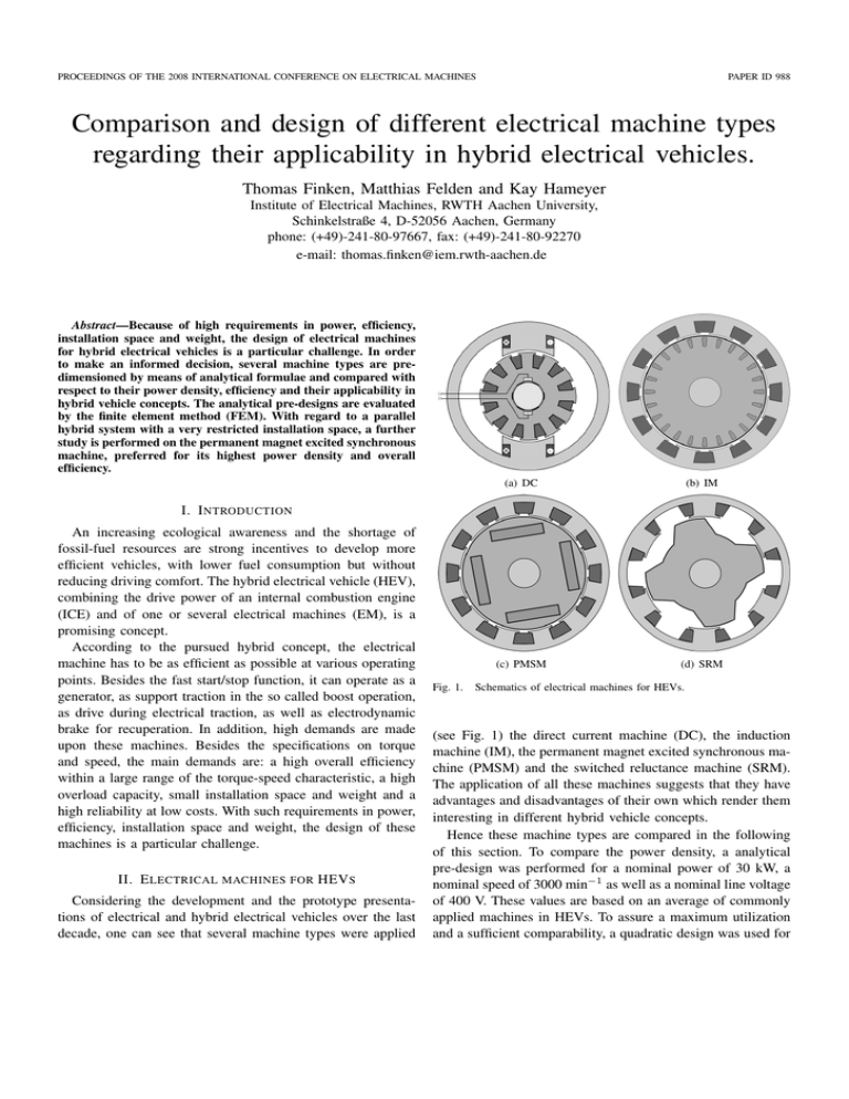
PROCEEDINGS OF THE 2008 INTERNATIONAL CONFERENCE ON ELECTRICAL MACHINES PAPER ID 988 Comparison and design of different electrical machine types regarding their applicability in hybrid electrical vehicles. Thomas Finken, Matthias Felden and Kay Hameyer Institute of Electrical Machines, RWTH Aachen University, Schinkelstraße 4, D-52056 Aachen, Germany phone: (+49)-241-80-97667, fax: (+49)-241-80-92270 e-mail: thomas.finken@iem.rwth-aachen.de Abstract—Because of high requirements in power, efficiency, installation space and weight, the design of electrical machines for hybrid electrical vehicles is a particular challenge. In order to make an informed decision, several machine types are predimensioned by means of analytical formulae and compared with respect to their power density, efficiency and their applicability in hybrid vehicle concepts. The analytical pre-designs are evaluated by the finite element method (FEM). With regard to a parallel hybrid system with a very restricted installation space, a further study is performed on the permanent magnet excited synchronous machine, preferred for its highest power density and overall efficiency. (a) DC (b) IM (c) PMSM (d) SRM I. I NTRODUCTION An increasing ecological awareness and the shortage of fossil-fuel resources are strong incentives to develop more efficient vehicles, with lower fuel consumption but without reducing driving comfort. The hybrid electrical vehicle (HEV), combining the drive power of an internal combustion engine (ICE) and of one or several electrical machines (EM), is a promising concept. According to the pursued hybrid concept, the electrical machine has to be as efficient as possible at various operating points. Besides the fast start/stop function, it can operate as a generator, as support traction in the so called boost operation, as drive during electrical traction, as well as electrodynamic brake for recuperation. In addition, high demands are made upon these machines. Besides the specifications on torque and speed, the main demands are: a high overall efficiency within a large range of the torque-speed characteristic, a high overload capacity, small installation space and weight and a high reliability at low costs. With such requirements in power, efficiency, installation space and weight, the design of these machines is a particular challenge. II. E LECTRICAL MACHINES FOR HEV S Considering the development and the prototype presentations of electrical and hybrid electrical vehicles over the last decade, one can see that several machine types were applied Fig. 1. Schematics of electrical machines for HEVs. (see Fig. 1) the direct current machine (DC), the induction machine (IM), the permanent magnet excited synchronous machine (PMSM) and the switched reluctance machine (SRM). The application of all these machines suggests that they have advantages and disadvantages of their own which render them interesting in different hybrid vehicle concepts. Hence these machine types are compared in the following of this section. To compare the power density, a analytical pre-design was performed for a nominal power of 30 kW, a nominal speed of 3000 min−1 as well as a nominal line voltage of 400 V. These values are based on an average of commonly applied machines in HEVs. To assure a maximum utilization and a sufficient comparability, a quadratic design was used for PROCEEDINGS OF THE 2008 INTERNATIONAL CONFERENCE ON ELECTRICAL MACHINES each machine. The analytical pre-designs were validated by finite element computations (FE), with the in-house software iMOOSE [1]. Parameterized geometrical models were used to generate the FE-models based on the geometry determined by the analytical design. By this means, the analytically calculated values of the induced voltage, the torque, the power and the expected air-gap induction were verified. An average deviation from the numerical simulation of about 2-3% has been found, thus the analytical design is deemed accurate enough. Furthermore, iron losses were calculated to determine the overall efficiency in combination with copper losses and approximate mechanical losses. A. DC-machine The DC machine allows the simplest regulation and, due to the possibility to connect this machine directly to the vehicle‘s battery, no complex power electronic is required. However, for powers higher than 20 kW, DC machines require commutating poles and compensation windings, so they are larger and more expensive. Due to the missing possibility of field weakening, the permanent magnet excitation, which would increase the machine‘s power density, is not feasible. Another disadvantage is the commutator and its brushes, which decreases the reliability and increases the maintenance costs. Most losses of the DC machine occur in the rotor, which makes it necessary to add a complex cooling system at high power and restricts the overload capacity. The analytical pre-design of the DC machine, performed according to [2], gives a volume of 19.2 dm3 and a power density of 1.6 kW/dm3 (Table I). These values result from a volume determination depending on the pole pair number p. The volume decreases significantly by increasing p in the range of small pole numbers, increasing the pole pair number beyond p = 6 gives only small improvements. However, increasing the pole number also increases the iron losses and thus decreases the overall efficiency. A pole pair number of p = 5 was chosen as a compromise solution. In summary, the DC machine has a moderate power density, a small efficiency and reliability but has the advantage of low costs and simple controllability, especially for small rated powers. PAPER ID 988 copper losses are reduced and accordingly the IM provides a wide speed range in combination with a comparatively good efficiency at high speeds. The required magnetization current and the copper losses in the rotor decrease the efficiency in the range of nominal speed compared to PMSMs. A disadvantage is the heat in the rotor as a result of the losses, which requires cooling and restricts overload capacity. Furthermore, an air gap as small as possible is necessary to decrease the magnetization current, but this requires tighten tolerances during fabrication and thus increases production costs. Here, the pre-designed IM (according to [2] and [3]) has a volume of 12.1 dm3 and a power density of 2.5 kW/dm3 . The pole pair number is p = 2, since this gives the best nominalto maximum-speed ratio and the best performance. Due to its advantages, the IM is the most commonly used machine in electrical vehicles. C. PMSM The excitation of the PMSM is provided by permanent magnets in the rotor. This machine benefits from the high energy density of the magnets, because the permanent magnet excitation requires little space. Since no excitation current is required, the PMSM provides a high overall efficiency in the range of nominal speed. The dominant losses of the PMSM are the iron losses, which mostly occur in the stator, so they can be easily dissipated by a case cooling system. Hence, the PMSM exceeds the IM in power density and efficiency. Its major disadvantage is the high costs of rare-earth magnets such as NdFeB. Another disadvantage is the additional current component required for field weakening, whereby higher stator losses occur and the efficiency decreases at high speeds. Furthermore the overload capacity is restricted by the magnet characteristics. To prevent them from irreversible demagnetization, high magnet temperatures in combination with high stator currents must be avoided - a reliable temperature detection is essential. The analytically pre-designed PMSM has a volume of 4.9 dm3 and a power density of 6.1 kW/dm3 - the design was performed by the in-house software ProMotor [4] following the design rules in [5]. As a result of their advantages the TABLE I R ESULT OF ANALYTICAL ROUGH DESIGN . B. Induction machine Induction machines with squirrel-cage rotor belong, as well as the DC machine, to the most technically mature machines, but they offer a higher power density and a better efficiency when compared to the DC machine. The dominant losses in IM machines are the copper losses. Due to the lower magnetization current in the range of field weakening, the number of pole pairs p maximum efficiency η rotor diameter Dr (mm) active length li (mm) outer diameter Da (mm) length with end windings la (mm) volume Va (dm3 ) power density (kW/dm3 ) DC 5 84% 239.5 69.8 430 132 19.2 1.6 IM 2 89% 162 127 258 232 12.1 2.5 PMSM 6 97% 136.8 140.8 196.3 161.5 4.9 6.1 SRM 12/8 88% 159 159 269 207 11.8 2.6 PROCEEDINGS OF THE 2008 INTERNATIONAL CONFERENCE ON ELECTRICAL MACHINES PMSM belongs to the most suitable machines for HEVs. Moreover, decreasing magnet costs are making PMSMs more appealing nowadays. D. Switched reluctance machine The principle of the SRM has been well known for a long time, but it was not applicable until the progress of power electronics. The SRM provides a power density and efficiency comparable to the IM. However, it has a simple construction without rotor winding and with concentrated stator windings, and therefore a better thermal characteristic. In addition, it is cost-effective in production and low-maintenance. To reach a high power density, a high air-gap induction is recommended - this however increases acoustic noise radiation. Measures for noise reduction decrease the power density and diminish the appeal of the SRM compared to the IM. Another disadvantage is the high torque ripple at low speeds. In addition the control of the SRM is more complicated than that of a three-phase drive, due to the high non-linearity of the determination of the current-switching angle. Therefore, the SRM was used in only a few prototypes of HEVs, until now. The pre-designed SRM (referring to [6]) has a volume of 11.8 dm3 and a power density of 2.6 kW/dm3 . The design of the SRM is a 12/8 machine, that means it has 12 stator slots and 8 rotor slots. E. Comparison and applicability in HEVs As a result of the previous discussion, the machine characteristics and their advantages and disadvantages are summarized in Table II. The direct current machine has a good technical maturity at low costs for machine and power electronics. But it offers the lowest power density and a bad efficiency. Furthermore it provides an insufficient reliability and requires a high amount of maintenance. The disadvantages exceed the advantages, so that the DC machine does not achieve the high requirements of an HEV. The induction machine features the best reliability at low production costs. It has the best average overall efficiency over the whole speed range, but its maximum efficiency does not reach the values of a PMSM. So the IM is advantageous if TABLE II E VALUATION OF THE ELECTRICAL MACHINES . power density efficiency costs reliability technical maturity controlability, costs DC ⊕ ⊕ ⊕⊕ IM ⊕ ⊕⊕ ⊕⊕ ⊕ PMSM ⊕⊕ ⊕⊕ ⊕ SRM ⊕ ⊕ ⊕ ⊕⊕ ⊕ very good good neutral bad very bad PAPER ID 988 a good efficiency over a wide speed range is required. But it only allows a moderate power density and a complicated and expensive field oriented control is required to reach high powers and dynamics. The switched reluctance machine is comparable in power density and efficiency with the IM, but inferior in the remaining points. Its main disadvantages, and exclusion criterion until now, has been the high torque ripple at low speeds and a significant acoustic noise radiation The permanent magnet synchronous machine offers the best power density; this permits a high power machine with small weight and even in the restricted installation space of a vehicle‘s engine compartment. It offers the best maximum efficiency in a defined speed range. For these reasons the PMSM may be most suitable to achieve a fuel saving hybrid electrical vehicle. However, due to its rare-earth magnets, it is the most expensive machine type as well. Comparing these results with several other machine comparisons in papers, reports or surveys like [7]-[11] shows distinctive similarities. The machine choice for hybrid electrical vehicles depends on the hybrid systems and its demands. In a series hybrid system, the electrical machines must be designed for the maximum vehicle power and the full speed range. Using an IM would be advantageous in this case, because of its good efficiency over a wide speed range and its low costs. A PMSM designed for the full vehicle power is more expensive, but is preferable if installation space and weight are the deciding factors. In a parallel (and power-split) hybrid system, the speed range depends on the connection to the gear box, the gearselection strategy and the HEV functionality, but typically it is restricted to lower speeds. Here the application of a PMSM is appropriate, due to its high efficiency at low speeds. The high power density minimizes the installation space and simplifies the integration into the driveline. Due to the comparatively lower machine power, required in the parallel system, the costs are also less significant. The choice of the machine type also depends on the control strategy of the hybrid electrical vehicle. It is to be determined in which operation points the electrical machine will be used. That means, the frequency distribution of the operation points during a drive cycle has to be considered. In Fig. 2 an exemplary frequency distribution for a parallel hybrid vehicle is depicted. Most operation points are in the range of low speeds up to 2000 min−1 , the maximum speed does not exceed 6000 min−1 - so the operation points are distributed over a limited speed range. According to this, we have to choose an electrical machine which has its best efficiency at lower speeds. In Fig. 3 the exemplary efficiency map of different machine types is depicted. The lines are equipotential lines, that surround the range of an efficiency η > 85%. The PMSM PROCEEDINGS OF THE 2008 INTERNATIONAL CONFERENCE ON ELECTRICAL MACHINES PAPER ID 988 has its best efficiency at low speed whereas the induction machine and the SRM have their best efficiency at higher speeds and over a wider speed range. In this case the PMSM would be the best choice. But if most of the operation points are at higher speeds or over a wide speed range, the IM should be preferred. III. F URTHER STUDY ON THE PMSM With regard to a parallel hybrid system with very restricted installation space, the permanent magnet excited synchronous machine (PMSM) was chosen, and a quantitative study of its power density and overall efficiency is presented. A. Variation of the pole pair number The pole pair number p influences the rotor size and thus the volume Va of a machine; considering the design of a machine with a given power - the higher the pole pair number the smaller the rotor diameter. Furthermore the stator-yoke height and the length of the end winding take up less room with increasing pole pair number. With a decreasing volume at constant power, the power density increases. But iron losses increase more than proportional by frequency, and the higher the pole pair number the higher the frequency of the stator currents and the higher the frequency of the alternating magnetic field. Because the iron losses are the dominant losses in PMSMs, the total losses increase significantly and thus the overall efficiency η decreases with increasing pole number. The characteristics of the volume Va and the overall efficiency η are depicted in Fig. 4. High pole pair numbers result in smaller volumes and thus higher power densities. However, the increase of power density (∝ 1/Va ) flattens with increasing pole numbers. Fig. 2. Exemplary frequency distribution during drive cycle. Fig. 3. Exemplary efficiency maps of different machines with constant power. B. Variation of the stator winding It is possible to apply different windings in PMSMs - the concentrated winding and the distributed winding, which both have their own advantages and disadvantages (see Fig. 5). The concentrated winding reduces the dimensions of the coil ends, and thus the copper losses, because end windings do not contribute to the torque generation but produce heat by copper losses. Moreover, the concentrated winding significantly increases the space factor and extends the automated manufacturing because rectangular conductors, preformed coils and segmented cores are possible to apply. Additionally torque ripples can be reduced by applying a non-symmetrical magnetic design. Distributed windings feature better winding factors than concentrated windings, so machines with distributed windings require a smaller number of turns, but its end windings Fig. 4. The PMSM depending on p and winding schemes. PROCEEDINGS OF THE 2008 INTERNATIONAL CONFERENCE ON ELECTRICAL MACHINES PAPER ID 988 best choice if a good overall efficiency and a low torque ripple is required. If the machine‘s power density is more essential, due to a small available space for instance, the machine with a concentrated winding has to be preferred. IV. C ONCLUSIONS (a) concentrated Fig. 5. (b) distributed Geometry and schematic windings. takes up more room and the winding volume increases. Also the higher slot number can increase the volume. The main advantage of the distributed winding is the possibility to vary the slot/pole ratio (zoning) and to apply short-pitching. By zoning (spreading a coil onto multiple slots q) and shortpitching (displacement of single or several turns into slots nearby) harmonics of the magnetic field can be weakened. By skilled application it is possible to get rid of the main harmonics and thus to minimize the torque ripple. In Fig. 4 the characteristics of the volume and the overall efficiency are shown. Due to the bigger end windings, the volume of the machine with distributed windings is always larger than that of the machine with concentrated windings. Zoning does not affect the volume significantly. But the zoning is not feasible any more, if the stator teeth are too thin due to the high slot numbers at high pole numbers. The machines with distributed winding have a better overall efficiency because of fewer harmonics and less iron losses the copper losses usually are not crucial. However, at small pole pair numbers the volume and thus the copper losses increase and the iron losses decrease. Here the copper losses are dominant; because of that the efficiency of the concentrated winding is better than that of the distributed winding for a pole pair number of two. However, due to the bad power density, machines with low pole pair numbers are not reasonable. In summary the machine with a distributed winding is be the To determine the most suitable electrical machine for hybrid electrical vehicles, several machine types were compared. To assure a good comparability, an analytical pre-design was performed for a nominal power of 30 kW and verified by the means of numerical FE simulation. The characteristics of the machines like the power density or the efficiency and their advantages and disadvantages were compared regarding their applicability in HEVs. With regard to a parallel hybrid system with very limited installation space, the permanent magnet excited synchronous machine (PMSM) was chosen for application and a further study, of its power density and overall efficiency was done. The effect of a varying pole pair number on the machine volume and on the efficiency was determined as well as the advantages and disadvantages of concentrated and distributed windings. The result of this paper indicates the PMSM as the most suitable machine for parallel hybrid systems. A result which is confirmed by the fact, that the PMSM is the mostly used machine type of today‘s HEVs. R EFERENCES [1] D. van Riesen, C. Monzel, C. Kaehler, C. Schlensok, G. Henneberger, “iMOOSE - an open-source environment for finite-element calculations”, IEEE Transactions on Magnetics vol.40,no.2,pp.1390-1393, 2004. [2] G. Müller, K. Vogt, B. Ponick, Berechnung elektrischer Maschinen, Wiley-VCH Verlag, 2008. [3] M. Schmitz, Fahrzyklusgerechte Auslegung einer Asynchronmaschine fuer Elektrofahrzeuge, PhD-thesis, Institute of Electrical Machines, RWTH Aachen University, Shaker Verlag, May 1998. [4] M. Schöning, K. Hameyer, “Virtual Product Development for Electrical Motors”, Proc. of 6th IEMDC, Antalya, 2007. Antalya, 2007. [5] S. Henneberger, Design and Development of a Permanent Magnet Synchronous Motor for a Hybrid Electric Vehicle Drive, PhD-thesis, Katholieke Universiteit Leuven, May 1998. [6] S. Risse and G. Henneberger, “Design and Optimization of a Reluctance Motor for Electric Vehicle Propulsion,”, ICEM , Helsinki, August 2000. [7] M. Zeraoulia, M.E.H. Benbouzid, D. Diallo, “Electric Motor Drive Selection Issues for HEV Propulsion Systems: A Comparative Study”, IEEE Trans. on Vehicular Technology, Vol.55, No.6, November 2006. [8] L. Chang, “Comparison of AC Drives for Electric Vehicles - A Report on Experts’ Opinion Survey”, IEEE AES Systems Magazine, August 1994. [9] M. Yabumoto, C. Kaido, T. Wakisaka, T. Kubota, N. Suzuki, “Electrical Steel Sheet for Traction Motors of Hybrid/Electrical Vehicles”, Nippon Steel Technical Report, No.87, July 2003. [10] J.G.W. West, “Propulsion systems for hybrid electric vehicles”, Electrical Machine Design for Electric and Hybrid-Electric Vehicles, IEE Colloquium on, pp. 1/1 - 1/9, October 1999. [11] C.C. Chan, “An overview of electric vehicle technology”, Proceedings of the IEEE, Volume 81, Issue 9, Page(s):1202 - 1213, September 1993.


