PRODUCT DISCONTINUATION - 3M™ ESPE™ MDI Mini Dental Implants
Sepember 1, 2016
3M discontinued the manufacture and sale of the 3M™ ESPE™ MDI Mini Dental Implant
product line on September 1, 2016.
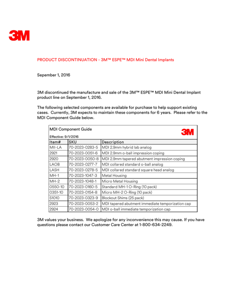
The following selected components are available for purchase to help support existing
cases. Currently, 3M expects to maintain these components for 6 years. Please refer to the
MDI Component Guide below.
MDI Component Guide
Effective: 9/1/2016
Item#
MII-LA
SKU
70-2023-0283-5
Descr iption
MDI 2.9mm hybrid lab analog
2921
2920
LAOB
LASH
MH-1
MH-2
0550-10
0351-10
S1010
2923
2924
70-2023-0051-6
70-2023-0050-8
70-2023-0277-7
70-2023-0278-5
70-2023-1047-3
70-2023-1048-1
70-2023-0160-5
70-2023-0154-8
70-2023-0323-9
70-2023-0053-2
70-2023-0054-0
MDI 2.9mm o-ball impression coping
MDI 2.9mm tapered abutment impression coping
MDI collared standard o-ball analog
MDI collared standard square head analog
Metal Housing
Micro Metal Housing
Standard MH-1 O-Ring (10 pack)
Micro MH-2 O-Ring (10 pack)
Blockout Shims (25 pack)
MDI tapered abutment immediate temporization cap
MDI o-ball immediate temporization cap
3M values your business. We apologize for any inconvenience this may cause. If you have
questions please contact our Customer Care Center at 1-800-634-2249.
3M™ ESPE™ MDI
Mini Dental Implants
Product Guide
2
Table of Contents
Mini Dental Implant System
System Benefits and Features ............................... 3
Implant Surgical Protocols
Preoperative Planning ...................................... 14–17
Mini Dental Implants
1.8mm Diameter Implants .......................................
2.1mm Diameter Implants .......................................
2.4mm Diameter Implants ......................................
2.9mm Diameter Implants ......................................
Direct Restorative Protocols
Secure Hard Pick-Up Protocol........................ 18–19
Secure Soft Reline Protocol................................... 19
4
5
6
7
Indirect Restorative Protocol ............................ 20–21
Prosthetics
Metal Housings ......................................................... 8
O-Rings....................................................................... 8
2.9mm Implant Protocols
Surgical Protocol ............................................. 22–23
Impression and Temporization Protocol ............ 24
Prosthetic Flow Chart
Lab Analogs and Restorative Copings for
1.8mm, 2.1mm and 2.4mm Implants ...................... 9
Lab Analogs and Restorative Copings for
2.9mm Hybrid Implants ......................................... 10
Implant Motors and Accessories............................. 25
Instruments and Drivers
Site Preparation......................................................... 11
Drivers, Wrenches, Ratchet Extension
and Adapters ............................................................. 11
Surgical and Restorative Kit and Accessories
Surgical and Prosthetic Kit .................................... 12
Patient Demonstration Models ............................. 12
ACCESS Toothbrush ............................................... 12
Secure Denture Materials
Secure Hard Pick-Up Kit ........................................
Secure Soft Reline Kit ............................................
Secure Accessories .................................................
Blockout Shims ........................................................
13
13
13
13
Terms and Conditions................................................ 26
3
Indications
For all MDI implants:
•Long-Term Full Denture Stabilization
•Long-Term Partial Denture Stabilization
•Long-Term Fixation of Bridges
In addition for MDI 2.9mm implant:
•Long-Term Fixation of Single Crowns
4
1.8mm Diameter Implants —
standard thread
Selection of implants is based on bone quality, soft-tissue thickness and dental procedure.
O-Ball
Implants
1.8mm
10mm
13mm
OB-10
15mm
OB-13
OB-15
18mm
OB-18
1.8mm
Prosthetic
Head
4mm
2.7mm
Polished 2.5mm
Transgingival
Collar
Collared
O-Ball
Implants
10mm
13mm
15mm
18mm
Thread
Length
1.8mm
S1810OB
S1813OB
S1815OB
1.8mm
S1818OB
Prosthetic
Head
Polished
Threads
Non-Collared
O-Ball
Implants
4mm
2mm
10mm
13mm Thread
15mm Length
18mm
1.8mm
Square
Head
Implants
1.8mm
10mm
13mm
15mm
18mm
SH-10
SH-13
SH-15
SH-18
1.8mm
Prosthetic
Head
Polished
Transgingival
Collar
Collared
Square Head
Implants
Thread
Length
4mm
2.5mm
2.7mm
10mm
13mm
15mm
18mm
1.8mm
MDI Implant Selection Guide
Implant Type
1.8mm with Collar
1.8mm without Collar
2.1mm with Collar
2.1mm without Collar
2.4mm with Collar
2.4mm without Collar
2.9mm with Collar
D1*
3
3
3
3
NR
NR
NR
Bone Density*
D2*
D3*
NR
3
NR
3
NR
3
NR
3
3
3
3
3
3
3
D4*
NR
NR
NR
NR
NR
NR
NR
Soft-Tissue Depth
<2mm
≥2mm
NR
3
NR
3
NR
3
NR
3
NR
3
NR
3
NR
3
Minimum Buccolingual Width
Bone Width
≥4.8
≥4.8
≥5.1
≥5.1
≥5.4
≥5.4
≥5.9
Usually, there is more dense bone in the mandible (D1/D2) compared to less bone density (D2/D3) in the maxilla. The appropriate implant
diameter should be completely surrounded by a least 1.5mm of bone and the length should engage bone for the entire threaded portion
of the implant.
*D1 = Very Dense Bone; D2 = Porous; D3 = Porous; D4 = Very Soft Bone; NR = Not Recommended
5
2.1mm Diameter Implants —
standard thread
Selection of implants is based on bone quality, soft-tissue thickness and dental procedure.
O-Ball
Implants
2.1mm
10mm
13mm
IOB-10
15mm
IOB-13
18mm
IOB-15
IOB-18
1.8mm
Prosthetic
Head
Polished
Transgingival
Collar
Collared
O-Ball
Implants
Thread
Length
4mm
2.7mm
2.5mm
10mm
13mm
15mm
18mm
2.1mm
S1810IOB
S1813IOB
S1815IOB
S1818IOB
1.8mm
Prosthetic
Head
4mm
Polished
Threads
Non-Collared
O-Ball
Implants
2mm
10mm
13mm
15mm
18mm
Thread
Length
2.1mm
3M™ ESPE™ MDI
Mini Dental Implants
5mm
7mm
Mental Foramen
15mm
13mm
10mm
2.4mm
10mm
2.1mm
10mm
10mm
13mm
2.1mm
13mm
1.8mm
13mm
15mm
2.4mm
18mm
15mm
13mm
10mm
1.8mm
5mm
2.1mm
18mm
2.4mm
Minimum spacing to
accomodate metal housings
1.8mm
18mm
15mm
7mm
Mental Foramen
2.4mm
10mm
10mm
2.1mm
13mm
13mm
1.8mm
10mm
2.4mm
2.1mm
13mm
15mm
15mm
15mm
1.8mm
125%
2.4mm
15mm
2.1mm
2.4mm
2.1mm
15mm
1.8mm
5mm
Minimum spacing to
accomodate metal housings
1.8mm
18mm
18mm
18mm
Implant diameter in mm -
13mm
10mm
10mm
120%
2.4mm
2.1mm
Mental Foramen
2.4mm
2.1mm
10mm
13mm
13mm
1.8mm
10mm
2.4mm
2.1mm
13mm
1.8mm
15mm
15mm
18mm
18mm
2.4mm
2.1mm
Implant diameter in mm 1.8mm
7mm
Minimum spacing to
accomodate metal housings
1.8mm
15mm
2.4mm
2.1mm
18mm
1.8mm
18mm
3M Oral Care provides MDI radiographic transparencies at no charge.
Ask your 3M Oral Care implant representative for details.
O-Ball with Collar - 1.8mm, 2.1mm & 2.4mm
100%
Implant diameter in mm -
18mm
•Radiographic Transparency for MDI Implants with Collar
•Radiographic Transparency for MDI Implants without Collar
•Radiographic Transparency for 2.9mm MDI Implants
18mm
MDI Radiographic Transparencies
1-800-634-2499
www.3MESPE.com/implants
3M and ESPE are trademarks of 3M or 3M ESPE AG. Used under license in Canada.
70-2013-0372-7
MDI Implant Selection Guide
Implant Type
1.8mm with Collar
1.8mm without Collar
2.1mm with Collar
2.1mm without Collar
2.4mm with Collar
2.4mm without Collar
2.9mm with Collar
D1*
3
3
3
3
NR
NR
NR
Bone Density*
D2*
D3*
NR
3
NR
3
NR
3
NR
3
3
3
3
3
3
3
D4*
NR
NR
NR
NR
NR
NR
NR
Soft-Tissue Depth
<2mm
≥2mm
NR
3
NR
3
NR
3
NR
3
NR
3
NR
3
NR
3
Minimum Buccolingual Width
Bone Width
≥4.8
≥4.8
≥5.1
≥5.1
≥5.4
≥5.4
≥5.9
Usually, there is more dense bone in the mandible (D1/D2) compared to less bone density (D2/D3) in the maxilla. The appropriate implant
diameter should be completely surrounded by a least 1.5mm of bone and the length should engage bone for the entire threaded portion
of the implant.
*D1 = Very Dense Bone; D2 = Porous; D3 = Porous; D4 = Very Soft Bone; NR = Not Recommended
6
2.4mm Diameter Implants —
max thread
Selection of implants is based on bone quality, soft-tissue thickness and dental procedure.
O-Ball
Implants
2.4mm
10mm
MOB-10
13mm
15mm
MOB-13
MOB-15
18mm
MOB-18
1.8mm
Prosthetic
Head
Polished
Transgingival
Collar
Collared
O-Ball
Implants
Thread
Length
4mm
2.7mm
2.5mm
10mm
13mm
15mm
18mm
2.4mm
S1810MOB S1813MOB S1815MOB S1818MOB
1.8mm
Prosthetic
Head
Polished
Threads
Non-Collared
O-Ball
Implants
4mm
2mm
10mm
13mm
15mm
18mm
Thread
Length
2.4mm
Square
Head
Implants
2.4mm
10mm
MSH-10
13mm
15mm
MSH-13
MSH-15
18mm
MSH-18
1.8mm
Prosthetic
Head
Polished
Transgingival
Collar
Collared
Square Head
Implants
Thread
Length
4mm
2.7mm
2.5mm
10mm
13mm
15mm
18mm
2.4mm
MDI Implant Selection Guide
Implant Type
1.8mm with Collar
1.8mm without Collar
2.1mm with Collar
2.1mm without Collar
2.4mm with Collar
2.4mm without Collar
2.9mm with Collar
D1*
3
3
3
3
NR
NR
NR
Bone Density*
D2*
D3*
NR
3
NR
3
NR
3
NR
3
3
3
3
3
3
3
D4*
NR
NR
NR
NR
NR
NR
NR
Soft-Tissue Depth
<2mm
≥2mm
NR
3
NR
3
NR
3
NR
3
NR
3
NR
3
NR
3
Minimum Buccolingual Width
Bone Width
≥4.8
≥4.8
≥5.1
≥5.1
≥5.4
≥5.4
≥5.9
Usually, there is more dense bone in the mandible (D1/D2) compared to less bone density (D2/D3) in the maxilla. The appropriate implant
diameter should be completely surrounded by a least 1.5mm of bone and the length should engage bone for the entire threaded portion
of the implant.
*D1 = Very Dense Bone; D2 = Porous; D3 = Porous; D4 = Very Soft Bone; NR = Not Recommended
7
2.9mm Diameter Implants —
max thread
Selection of implants is based on bone quality, soft-tissue thickness and dental procedure.
O-Ball
Implants
2.9mm
10mm
MII-OB10
13mm
15mm
MII-OB13
MII-OB15
18mm
1.8mm
Prosthetic
Head*
MII-OB18
Polished
Transgingival
Collar
O-Ball
Implants
Thread
Length
4mm
2.9mm
1.9mm
10mm
13mm
15mm
18mm
2.9mm
*TiN Coating on Prosthetic Head
Tapered
Abutment
Implants
2.9mm
10mm
13mm
15mm
18mm
MII-T10
MII-T13
MII-T15
MII-T18
Tapered
Abutment
Implants
2.3mm
1.8mm
6° Taper
Taper Head
6mm
Polished
Transgingival
Collar
1.9mm
Thread
Length
2.9mm
10mm
13mm
15mm
18mm
2.9mm
3M™ ESPE™ MDI
Mini Dental Implants
5mm
7mm
Mental Foramen
15mm
13mm
10mm
2.4mm
10mm
2.1mm
10mm
10mm
13mm
2.1mm
13mm
1.8mm
13mm
15mm
2.4mm
18mm
15mm
13mm
10mm
1.8mm
5mm
2.1mm
18mm
2.4mm
Minimum spacing to
accomodate metal housings
1.8mm
18mm
15mm
7mm
Mental Foramen
2.4mm
10mm
10mm
2.1mm
13mm
13mm
1.8mm
10mm
2.4mm
2.1mm
13mm
15mm
15mm
15mm
1.8mm
125%
2.4mm
15mm
2.1mm
2.4mm
2.1mm
15mm
1.8mm
5mm
Minimum spacing to
accomodate metal housings
1.8mm
18mm
18mm
18mm
Implant diameter in mm -
13mm
10mm
10mm
120%
2.4mm
2.1mm
Mental Foramen
2.4mm
2.1mm
10mm
13mm
13mm
1.8mm
10mm
2.4mm
2.1mm
13mm
1.8mm
15mm
15mm
18mm
18mm
2.4mm
2.1mm
Implant diameter in mm 1.8mm
7mm
Minimum spacing to
accomodate metal housings
1.8mm
15mm
2.4mm
2.1mm
18mm
1.8mm
18mm
3M Oral Care provides MDI radiographic transparencies at no charge.
Ask your 3M Oral Care implant representative for details.
O-Ball with Collar - 1.8mm, 2.1mm & 2.4mm
100%
Implant diameter in mm -
18mm
•Radiographic Transparency for MDI Implants with Collar
•Radiographic Transparency for MDI Implants without Collar
•Radiographic Transparency for 2.9mm MDI Implants
18mm
MDI Radiographic Transparencies
1-800-634-2499
www.3MESPE.com/implants
3M and ESPE are trademarks of 3M or 3M ESPE AG. Used under license in Canada.
70-2013-0372-7
MDI Implant Selection Guide
Implant Type
1.8mm with Collar
1.8mm without Collar
2.1mm with Collar
2.1mm without Collar
2.4mm with Collar
2.4mm without Collar
2.9mm with Collar
D1*
3
3
3
3
NR
NR
NR
Bone Density*
D2*
D3*
NR
3
NR
3
NR
3
NR
3
3
3
3
3
3
3
D4*
NR
NR
NR
NR
NR
NR
NR
Soft-Tissue Depth
<2mm
≥2mm
NR
3
NR
3
NR
3
NR
3
NR
3
NR
3
NR
3
Minimum Buccolingual Width
Bone Width
≥4.8
≥4.8
≥5.1
≥5.1
≥5.4
≥5.4
≥5.9
Usually, there is more dense bone in the mandible (D1/D2) compared to less bone density (D2/D3) in the maxilla. The appropriate implant
diameter should be completely surrounded by a least 1.5mm of bone and the length should engage bone for the entire threaded portion
of the implant.
*D1 = Very Dense Bone; D2 = Porous; D3 = Porous; D4 = Very Soft Bone; NR = Not Recommended
8
Prosthetics
Metal
Housings
Height
Diameter
MH-1
Metal Housing
3.6mm
4.7mm
MH-2
Micro Metal Housing
3.3mm
4.3mm
MH-3
O-Cap
3.0mm
4.1mm
4.7mm
O-Rings
MH-3
3.3mm
MH-2
3.6mm
MH-1
3mm
Chung, K.-H., Chan, D., Gustafson, M. Retentive Characteristics of NarrowDiameter Implant-Retained; Overdentures after Fatigue Loading. J. Dent. Res.,
91 (Spec. Iss. A): 1433, 2012.
4.3mm
4.1mm
Replacement O-Ring for MH-1
0550-01
Standard MDI O-Ring
0550-10
Standard MDI O-Ring (10 pack)
0550-25
Standard MDI O-Ring (25 pack)
0550-01
Replacement O-Ring for MH-2 and MH-3
0351-01
Micro MDI O-Ring
0351-10
Micro MDI O-Ring (10 pack)
0351-25
Micro MDI O-Ring (25 pack)
0351-01
9
Prosthetic Flow Chart
1.8mm, 2.1mm and 2.4mm Implants
Collared O-Ball Implants
Non-Collared O-Ball Implants
Collared Square Head Implants
Corresponds with Lab Analog LAOB
Corresponds with Lab Analog 5118
Corresponds with Lab Analog LASH
1.8mm
diameter
2.1mm
diameter
2.4mm
diameter
1.8mm
diameter
2.1mm
diameter
2.4mm
diameter
1.8mm
diameter
2.4mm
diameter
OB-10 — 10mm — IOB-10 — 10mm —MOB-10
S1810OB—10mm—S1810IOB—10mm—S1810MOB
SH-10 — 10mm —MSH-10
OB-13 — 13mm — IOB-13 — 13mm —MOB-13
S1813OB—13mm—S1813IOB—13mm—S1813MOB
SH-13 — 13mm —MSH-13
OB-15 — 15mm — IOB-15 — 15mm —MOB-15
S1815OB— 15mm —S1815IOB—15mm—S1815MOB
SH-15 — 15mm — MSH-15
OB-18 — 18mm — IOB-18 — 18mm —MOB-18
S1818OB—18mm—S1818IOB—18mm—S1818MOB
SH-18 — 18mm —MSH-18
Collared O-Ball
Analog
Non-Collared
O-Ball Analog
Collared Square
Head Analog
LAOB
5118
LASH
Metal Housings
Standard
Micro
O-Cap
MH-1
MH-2
MH-3
Blockout
Shim
O-Ball Restorative
Copings
O-Ball/
Square Head
Waxing Coping
S1010
O-Rings
0550-10
0351-10
2921
2924
O-Ball
Impression
Coping
O-Ball
Immediate
Temporization
Cap
S4118
Waxing Coping
10
Prosthetic Flow Chart cont.
2.9mm Hybrid Implants
O-Ball Implants
Tapered Abutment Implants
2.9mm diameter
2.9mm diameter
10mm — MII-OB10
10mm — MII-T10
13mm — MII-OB13
13mm — MII-T13
15mm — MII-OB15
15mm — MII-T15
18mm — MII-OB18
18mm — MII-T18
Blockout
Shim
S1010
Metal Housings
Standard
Micro
O-Cap
MH-1
MH-2
MH-3
O-Rings
0550-10
Tapered Abutment
Restorative Copings
O-Ball
0351-10
Tapered
Abutment
2.9mm Hybrid Lab Analog
MII-LA
2920
2923
Tapered
Tapered
Abutment
Abutment
Immediate
Impression
Temporization
Coping
Cap
2922
Tapered
Abutment
Waxing
Coping
2.9mm Hybrid Lab Analog Kits
O-Ball Restorative Copings
2921
2924
S4118
O-Ball
Impression
Coping
O-Ball
Immediate
Temporization
Cap
O-Ball
Waxing
Coping
MII-LAKO
2.9mm Hybrid Lab Analog Kit
(O-Ball)
2921
MII-LA
MII-LAKT
2.9mm Hybrid Lab Analog Kit
(Tapered Abutment)
2920
2924
MII-LA
2923
11
Instruments and Drivers
Site Preparation
1325
Ridge Mapping Caliper
S1011
1.1mm MDI Surgical Drill (sterile, single use)
2010
1.7mm MDI Standard Marking Pilot Drill
1.7mm
1.1mm
17mm
1325
S1011
2010
Drivers, Wrenches, Ratchet Extension and Adapters
S9030
MDI Finger Driver
S9032
MDI Winged Thumb Wrench
8070
Graduated Torque Wrench
8071
4x4 Adapter for Graduated Torque Wrench
1030
Titanium Locking Pliers for Implants
8016
16mm Ratchet Wrench Extension
S7015
MDI Ratchet Adapter Long
S7011
MDI Ratchet Adapter Medium
S7007
MDI Ratchet Adapter Short
13mm
S9030
S9032
8070*
8071
*8070 comes with 8071 Adapter. 8071 is a replacement adapter.
16mm
1030
8016
13mm
S7015
9mm
S7011
5mm
S7007
12
Surgical and Restorative Kit
and Accessories
Surgical and Prosthetic Kit
S1807
Includes:
MDI Surgical Standard Kit
S1011
1.1mm MDI Surgical Drill (Qty. 3)
8070
Torque Wrench up to 70 Ncm
MDI Finger Driver
S9030
MDI Winged Thumb Wrench
S9032
MDI Ratched Adapter Short – 5mm
S7007
Blockout Shims (Pack of 25)
S1010
MDI Small Surgical Box
S1807
0121
Patient Demonstration Models
SMDI-001
MDI Model Mandible – Clear Acrylic Base
SMDI-003
MDI Model Maxilla Base
SMDI-004
MDI Model Mandible – Pink Acrylic Base
SMDI-005
MDI Hybrid Model
ACCESS Toothbrush
6008-12
ACCESS Toothbrush Bristle Density #1 Hard
(Pack of 12)
6009-12
ACCESS Toothbrush Bristle Density #2 Soft
(Pack of 12)
SMDI-001
SMDI-003
SMDI-004
SMDI-005
13
Secure Denture Materials
Secure Hard Pick-Up Kit
8720
Includes:
Secure Hard Pick-Up Kit
50ml safety cartridge of hard pick-up material
10ml adhesive
Accessories
8721
Secure Hard Refill (Pack of 2)
8720
Secure Soft Reline Kit
8120
Includes:
Secure Soft Reline Kit
50ml safety cartridge of soft reline material
10ml glazing catalyst
8120
10ml glazing base
10ml adhesive
Accessories
Secure Accessories
8366-10
Insertion Tips Type 1 (Pack of 10)
8448-10
Mixing Tips Type 8 (Pack of 10)
8449-12
Adhesive Brushes (Pack of 12)
8366-10
8448-10
8449-12
9mm
Shims to block out Secure Hard
Pick-Up under the metal housings.
Trim to appropriate length.
Blockout Shims
S1010
Blockout Shims (Pack of 25)
S1010
14
Implant Surgical Protocols
Preoperative Planning
Careful case planning and appropriate patient selection criteria are necessary for a successful MDI treatment.
This includes a preliminary medical and dental case history, a current health status of the patient, adequate
bone density and volume, the ability of the patient to understand and implement appropriate oral hygiene.
Bone height, bone width and anatomical structures can be revealed by x-ray. Bone width can also be mapped
with ridge mapping calipers under local anesthesia. While most cases do not require a soft tissue flap, it is
within the discretion of the clinician to determine whether a case requires a flap. It is recommended that
clinicians who use MDIs are able to carry out flap surgery.
Denture Stabilization in the Mandible
After patient selection and checkup, the number of required MDI implants is defined (at least four). Discuss
the treatment with the patient in detail. Subsequently, the lower denture of the patient is made or modified
and best implant positions are defined. Distance of MDI implants are at least 5mm apart. In the lower jaw the
implants should be at least 7mm anterior to the mental foramen.
1. Site Preparation
2. Use of Finger Driver
•Entry points for each MDI implant are marked on
the patient’s tissue via bleeding points or a marker.
•Open the MDI implant vial.*
•The 1.1mm Pilot Drill is delicately placed over the
entry point and lightly pumped up and down until
the cortical plate is penetrated. No incision is
necessary in most cases.
•The average depth is one-third to one-half the
threaded length of the implant. Sterile irrigation
is utilized throughout the drilling procedure.
•In extremely dense bone an extended penetration
may be required.
•The pilot hole depth should never equal the length
of the implant, as the tip of the drill is wider than
the tip of the implant.
•Recommended motor RPM = 1200–1500
•Carry implant to the site using the vial cap that
is attached to it. Do the first turns with the vial
cap until resistance is met. Alternatively, use the
Titanium Locking Pliers to grasp the body of the
implant and separate it from the vial cap. Attach
the Finger Driver to the head of the implant. (It has
a friction grip o-ring and can be used as a carrier
to the patient's mouth, as well as a surgical driver).
•After inserting the implant into the pilot opening
through the attached gingiva, rotate clockwise
while exerting downward pressure.
•The Finger Driver allows slight corrections of
angulation in the beginning.
•With increasing resistance replace the Finger
Driver by the Winged Thumb Wrench.
•Throughout the placement procedure, the
implant should be advanced slowly into the
bone to allow time for bone relaxation and
minimize the thermal effect.
S1011
A 1.5mm Disposable Tissue Punch can be used to remove
mobile mucosa.
S9030
OB-13
IOB-13
*All MDI Implants are delivered sterile.
15
3. Use of the Winged Thumb Wrench
Use the Winged Thumb Wrench to thread the implant
into place.
S9032
4. Use of the Graduated Torque Wrench
with Ratchet Adapter
•The Graduated Torque Wrench will then finalize the
insertion process.
•Grasp the wrench (with the directional arrow facing
clockwise) and engage the square neck of the Ratchet
Adapter into the square opening of wrench.
•This final stage of MDI implant placement requires
slow, carefully controlled ratchet turns.
•The ideal implant position allows the abutment head
to protrude from the gingival soft tissue at its full
length but with no neck or thread portions visible.
•Advance the implant with the Torque Wrench to a
minimum of 35 Ncm to allow immediate load.
•If a resistance of at least 35 Ncm cannot be reached
a temporary soft-loading without metal housings is
­recommended.
•Record torque reading for each implant.
S7007
MDI Torque
Recommendations
8070
• Do not exceed
45 Ncm
during implant
placement.
• A minimum
of 35 Ncm of
resistance upon
final insertion is
recommended for
immediate load.
CAUTION IN DENSE BONE: If torque exceeds 45 Ncm unscrew the
implant and deepen the drill hole to 2/3 of implant length.
5. Final Implant Positioning
A minimum of four MDI implants is required to stabilize
a full lower denture.
IMPORTANT: The decisive factors for a successful treatment are the
primary stability of the implants and the compliance of the drilling and
loading protocol.
Ideal Implant Position
16
Implant Surgical Protocols cont.
Denture Stabilization in the Maxilla
Please note that in the maxilla there are difficult anatomical conditions for the insertion of implants (anatomy of
the alveolar ridge, bone density and soft tissue). Therefore, carefully consider whether the implants should be
inserted transgingivally or under direct vision with a flap. The softer maxillary bone generally requires the use
of implants with a more aggressive max thread (2.4mm and 2.9mm MDI implants). When placed in the upper
jaw, the position of the sinus in relation to the bone needs to be assessed. A minimum of six mini-implants in
the maxilla is recommended, which must be inserted at least 5mm apart in order to leave enough space for the
metal housings.
1. Site Preparation
2. Use of Finger Driver
•Entry points for each MDI implant are marked on
the patient’s tissue via bleeding points or a marker.
•Open the MDI implant vial.*
•The 1.1mm Pilot Drill is delicately placed over the
entry point and lightly pumped up and down until
the cortical plate is penetrated. No incision is
necessary in most cases.
•The average depth is one-third to one-half the
threaded length of the implant. Sterile irrigation
is utilized throughout the drilling procedure.
•Carry implant to the site using the vial cap that
is attached to it. Do the first turns with the vial
cap until resistance is met. Alternatively, use the
Titanium Locking Pliers to grasp the body of the
implant and separate it from the vial cap. Attach
the Finger Driver to the head of the implant. (It has
a friction grip o-ring and can be sued as a carrier
to the patient's mouth, as well as a surgical driver).
•The pilot hole depth should never equal the length
of the implant, as the tip of the drill is wider than
the tip of the implant.
•After inserting the implant into the pilot opening
through the attached gingiva, rotate clockwise
while exerting downward pressure.
2.1 and 2.4mm
diameter MDI
implants require
use of the 1.1mm
Pilot Drill
(Item S1011).
•With increasing resistance replace the Finger
Driver by the Winged Thumb Wrench.
•The Finger Driver allows slight corrections of
angulation in the beginning.
•Throughout the placement procedure the
implant should be advanced slowly into the
bone to allow time for bone relaxation and
minimize the thermal effect.
2.9mm diameter
MDI implants may
require use of a
disposable tissue
punch followed
by the 1.7mm Pilot
Drill (Item 2010).
Optionally, in dense
bone a larger drill
may be necessary
to widen the
drill channel.
S1011
A 1.5mm Disposable Tissue Punch can be used
to remove mobile mucosa.
2010
S9030
*All MDI Implants are delivered sterile.
MOB-13
MII-OB13
17
3. Use of the Winged Thumb Wrench
S9032
4. Use of the Graduated Torque Wrench
with the Ratchet Adapter
Connect the Graduated Torque Wrench and record
torque reading for each implant. Confirm at least
35 Ncm of resistance.
If there is less than 35 Ncm of resistance — which
might ­frequently be the case in maxillar bone, assess
the situation, consider moving the implant, a larger
implant and/or allow osseointegration.
S7007
5. Final Implant Positioning
A minimum of six MDI implants are required to
stabilize a full maxillary denture.
IMPORTANT: The decisive factors for a successful treatment are the
primary stability of the implants and the compliance of the drilling and
loading protocol.
8070
MDI Torque
Recommendations
• Do not exceed
45 Ncm
during implant
placement.
• A minimum
of 35 Ncm of
resistance upon
final insertion is
recommended.
18
Direct Restorative Protocols
Secure Hard Pick-Up Protocol
1. Relieve denture to accommodate implants
2. Trim Blockout Shims to appropriate length and
3. Place Metal Housings on each implant and
4. Apply a thin layer of adhesive to the tissue-contact
5. Extrude Secure Hard Pick-Up material
6. Seat denture in patient’s mouth and have patient
and metal housings, creating individual holes
or a trough.
check for passive fit over shims. Place denture
in patient’s mouth and check for passive fit
over implants and housings.
directly onto Metal Housings and into the
troughed denture.
place one shim on each implant to block out
undercuts and prevent acrylic from locking onto
the implants.
surface of the denture.
­ pply normal bite pressure in centric occlusion
a
and allow 7–9 minutes for Secure Hard Pick-Up
material to set. It is advised to assist holding the
patient’s jaw closed.
19
7. Remove denture and all blockout shims, trim and
polish. Seat the final denture and inform the patient
to keep the denture in place for the first 48 hours
after placement to prevent tissue overgrowth.
Removable O-Ring (0550-01)
housed inside metal housing.
Denture
Secure Soft Reline Protocol
May be necessary on occasional case when
implants are placed in softer bone in the
mandible with no sufficient primary stability.
•Grind down denture base at least 1mm and
relieve denture to accommodate the prosthetic
heads of each implant.
•Roughen the tissue-contact surface of the
denture with an acrylic bur and degrease the
surface with isopropyl alcohol.
•Apply a thin coat of adhesive.
•Extrude Secure Soft Reline material onto the
tissue-contact surface of the denture.
•Place the denture in the patient’s mouth and
ask patient to apply normal bite pressure in
centric occlusion.
•Allow seven minutes for Secure Soft Reline
material to set.
•Remove denture and trim excess material with
fine scissors or a surgical blade.
•Mix equal drops of glazing base and catalyst.
•Use a brush to apply the mixture to the
corresponding margins.
•DO NOT remove the palate of a maxillary denture
during this stage.
•Ask the patient to keep the denture in place for
the first 48 hours after placement to prevent tissue
overgrowth.
• Four to six months after soft load, the soft liner
is replaced with a hard pick-up of the MDI Metal
Housings (follow instructions for “Secure Hard
Pick-Up Protocol”) to increase the level of retention.
•After osseointegration the palatinal plate in maxillary
denture can be progressively removed, if desired.
20
Indirect Restorative Protocol
1. Seating the Copings
Snap the appropriate Impression Copings directly
onto each appropriate MDI Implant.
NOTE: Soft tissue may prevent full engagement of the coping
on implants seated too deeply into soft tissue. In such a case,
it is recommended to take an impression of the O-Ball head of
the implant without impression copings.
2. Seating the Impression
Standard crown and bridge impression techniques
are used to pick up the impression copings.
3M™ ESPE™ Impregum™ Polyether Impression
Material is recommended for implant impressions.
3. Removal of the Impression
Once the impression has fully set, carefully remove
the tray from the patient’s mouth and confirm all
impression copings have been captured accurately
in the impression.
21
4. Insertion of the
Lab Analogs
LAOB
MDI Collared
O-Ball Analog
This can be done in the clinic or at
the dental laboratory.
Confirm the appropriate MDI Lab
Analog will be inserted by reviewing
the type of Implant used in the case.
Insert a lab analog into each coping
and fabricate a stone model.
5. Fabrication of the model
Use standard stone model fabrication techniques to
form the model. Once the stone has set, carefully
remove the impression from the model.
5118
MDI Non-Collared
O-Ball Analog
LASH
MDI Collared
Square Head Analog
MII-LA
MDI Hybrid
Analog
22
2.9mm Implant Protocols
Surgical Protocol
The 3M™ ESPE™ MDI Mini dental implants 2.9mm system with max thread especially suitable for soft bone
(D2 or D3 bone).
1. Site Preparation
1a. Probe soft tissue at implant site and record ­
tissue thickness.
Soft Bone Drilling
Protocol (D3 Bone)
Entry divots are made with
a small round bur, then the
1.7mm MDI drill is used to
perforate the cortical plate.
Dense Bone Drilling
Protocol (D2 Bone)
1b. Remove soft tissue at implant site using a
1.5mm tissue punch, if desired.
1c. Create pilot hole using 1200–1500 rpm and
sterile irrigation.
Entry divots are made
with a small round bur.
Pilot holes then made
with the 1.7mm Pilot Drill
should have a depth
equal to approximately
1/2 the length of the
planned implant plus
the measurement of soft
tissue thickness. Drill to a
depth of 1/3 to 1/2 of the
threaded portion of the
selected implant. DO NOT
drill more than halfway into
a D2/D3 bone, because
the spiral implant is
self-tapping. Optionally,
in dense bone a larger
drill may be necessary to
widen the drill channel.
An endodontic stopper
is helpful in marking
appropriate depth.
2010
23
Implant Placement
!
Do not exceed 45 Ncm of torque
during placement.
2. Use of the Finger Driver
3. Use of the Winged Thumb Wrench
Insertion of the MDI implant begins with the vial
cap or with the Finger Driver and continues with
the Finger Driver until more torque is necessary.
Use the Winged Thumb Wrench to thread the implant
into place.
S9030
S9032
4. Use of the Graduated Torque
Wrench with the Ratchet Adapter
Insertion continues with the Ratchet Adapter
connected to the Graduated Torque Wrench.
To verify initial stability is sufficient for each implant,
­verify and record initial stability and confirm at least
35 Ncm of resistance.
S7007
8071*
8070
*Adapter 8071 included with Graduated Torque Wrench 8070.
Adapter also available separately.
5. Final Implant Positioning
The final position is reached when all threads are fully
integrated in the bone.
24
2.9mm Implant Protocols cont.
Impression and Temporization Protocol
1. Taking an Impression
A Pick-Up impression (transfer impression) is
made using the retentive impression coping.
2. Forming the Temporary Restoration
Once adjacent teeth are lubricated with petroleum
jelly, Tapered Abutment (2923) or O-Ball (2924)
Immediate Temporization Caps are seated on the
implants. 3M™ ESPE™ Protemp™ Plus Temporization
Material* is then extruded in the temporary crown
impression or stint and placed in the patient’s
mouth for 1 minute and 40 seconds to 2 minutes
and 50 seconds from the onset of mixing.
3. Finishing the Temporary Restoration
Refer to the temporary cement Instructions for Use.
*For more information on ordering 3M Oral Care products visit www.3M.com/dental
25
Implant Motors and Accessories
Implant and Endodontic System
AEU-6000
Basic Implant Surgery System,
Handpiece Sold Separately
AEU-6000
Implant and Oral Surgery System
AEU-7000E-70V
Implant Motor with Multi-Functional
Foot Pedal
AEU-7000E-70V
Handpieces
AHP-85P-I
AHP-85MB-CX
AHP-09
20:1 Reduction Contra Angle Handpiece
(200–1500 rpm)
High Torque Contra Angle Handpiece
(200–1500 rpm)
AseptiSpray
AHP-85P-I
*For more information on additional motors and handpieces, visit www.3M.com/dental
AHP-85MB-CX
AHP-09
26
Terms and Conditions
3M Oral Care is committed to help redefine
the evolving field of dentistry, with the goal
of providing products and services that
transform the way clinicians ­practice today.
MDI Mini Dental Implant System
Great care is taken in the selection of
materials, production methods, sterilization
and packaging of 3M Oral Care implants
and associated components. Strict
inspection procedures have been
established to ensure all 3M Oral Care
implant products are in compliance with
an array of regulatory standards.
3M Oral Care implant products are
manufactured under a certified ISO 13485
quality system and FDA’s Good
Manufacturing Practices (GMP). In addition,
they meet the stringent European Medical
Device Directive and thus can carry the
CE mark. 3M Oral Care implant products
have been cleared by the Food and Drug
Administration (FDA) to be marketed and
sold in the United States. This demonstrates
3M Oral Care’s commitment to quality and
patient safety.
Technical/Clinical Assistance
Please contact an authorized 3M Oral
Care distributor or the company at
www.3M.com/dental
• All prices are subject to change
without notice
• All graphics are by way of illustration only
(Not responsible for typographical errors)
• For more information online please visit
www.3M.com/dental
Ordering Information
Minimum Order: None.
Transportation: F.O.B. 3M Plant, Irvine, CA.
Backordered products shipped
F.O.B. freight prepaid and allowed.
Terms: Credit Card.
Prices: Subject to change without notice.
Shipping: There is no freight charge for
ground transportation. Next day, 2 day or 3
day available at additional charge.
Ordering Address:
3M Oral Care Customer Service
3M Center, Bldg 275-2W
St. Paul, MN 55144
PO Box 19582
Irvine, CA 92623-9582
Phone: 1-800-634-2249 x2
Fax: 1-800-986-9574
24 hour fax service available.
Website: www.3M.com/Implants
Quality
3M Oral Care implant products meet the
rigid specifications of the medical device
regulations. Many of the products and
components are subject to 100% inspection
during various stages of production. Any
identified quality issue with a 3M Oral Care
product should be immediately referred
to 3M Oral Care customer care group at
1-800-634-2249 x1. Upon confirmation
of the issue, customer will be sent a
replacement directly or if a credit is
warranted this will be made in the form
of original payment.
Packaging
MDI implants and sterile components utilize
packaging configurations that have been
validated to provide clean, sterile barriers for
a duration of at least five years. Each sterile
device includes a removable patient chart
label for future ­referencing and simplified
record keeping. Dental instrumentation and
components are provided non-sterile unless
other­wise noted.
Commitment
Our commitment is to provide the
dental profession with state of the art,
cost effective dental implants and
associated products, coupled with
competent, ­reliable customer service.
We stand ready to serve you at all times.
Please visit our website at www.3M.com/
dental to locate your 3M Oral Care office
for more ­information.
Return Policy
All returns must be authorized by a 3M Oral
Care representative prior to returning
product(s) for credit. All returns require a
Return Merchandising Authorization (RMA). To
obtain your return authorization call 1-800634-2249 x1. Items must be returned and
packaged in the original, unopened, and
undamaged packaging with the RMA number
clearly printed on the shipping label. Any
package received without a valid RMA number
clearly printed on the outside of the package
will be refused and returned to sender.
3M Oral Care reserves the right to assess a
handling fee on any overstock returns as
follows: 1–90 Days — 15% handling fee
(Unopened);
91+ Days — Will not be accepted.
Disposition of Products
Any returnable items must be shipped back
to 3M Oral Care to ensure compliance with
pedigree product tracking.
MDI Implant Products –
Limited Warranty
3M Oral Care warrants to the purchaser that its
dental implant products will be free from defects
in material and manufacture for the period stated
in the product literature for each product. If no
period is ­stated, the warranty period is 1 year
from the date of shipment. 3M ORAL CARE
MAKES NO OTHER WARRANTIES INCLUDING
ANY IMPLIED WARRANTY OF
MERCHANTABILITY OR FITNESS FOR A
PARTICULAR PURPOSE. User is responsible for
evaluating whether a product is appropriate for a
particular use or application.
3M Oral Care’s sole obligation and the buyer’s
sole remedy in the event of any claimed defect
shall be, at 3M Oral Care’s option, repair or
replacement of the p
­ roduct, or ­refund of the
purchase price. Written notice of claimed defect
must be received by 3M Oral Care within
reasonable time after discovery not to exceed
one year from the date of delivery. Except where
prohibited by law, 3M Oral Care shall not be
liable for any loss or damage arising from its
dental implant products, whether direct, ­indirect,
special, consequential, regardless of the theory
asserted, including warranty, contract,
negligence or strict liability. 3M Oral Care neither
­assumes, nor authorizes any other person to
assume on its behalf any additional liability or
responsibility in connection with its dental
implant products. Defects misuse, neglect,
accident or failure to follow recommended
procedures or ­instructions for use or by
modification by the buyer or user voids any
3M Oral Care ­implant product warranty.
CAUTION: United States laws restrict the sale
of any 3M dental implant p
­ roduct or device to
licensed physicians, dentists or dental ­specialists.
27
3M Oral Care
2510 Conway Avenue
St. Paul, MN 55144-1000 USA
Phone1-800-634-2249
Customer Care Center: 1-800-634-2249
www.3M.com/Implants
3M, 3M Science. Applied to Life., ESPE, Filtek, Impregum, Protemp and RelyX are trademarks of 3M
or 3M Deutschland GmbH. Secure is not a trademark of 3M. All other trademarks are property of their
respective owners. Used under license in Canada. © 3M 2016. All rights reserved. 70-2013-0366-9

