Compatible
Automation Server
PS-24V Power Supply
Enables StruxureWare Building
Operation v1.3
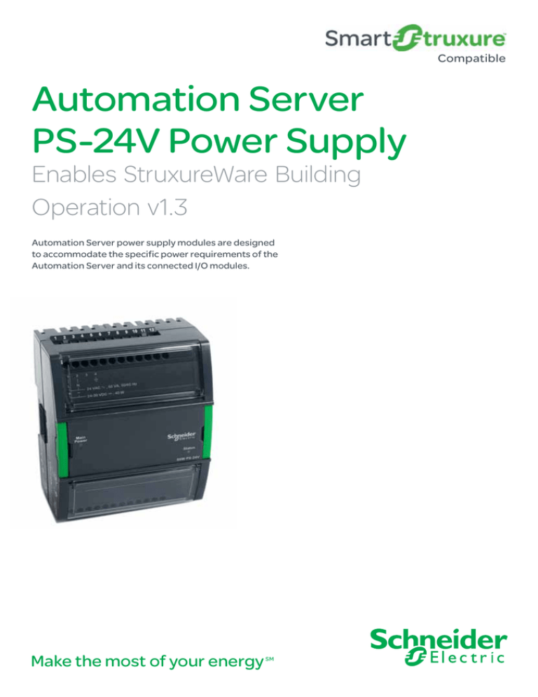
Automation Server power supply modules are designed
to accommodate the specific power requirements of the
Automation Server and its connected I/O modules.
Make the most of your energy
SM
2
Automation Server PS-24V Power Supply Module
Features
The PS-24V is a power supply module
that accommodates 24 VAC or 24 VDC
input power.
Reliable consistent output power
Each power supply module delivers reliable and
consistent output power of 24 VDC to the backplane.
Modular and scalable system
This power supply supports the Automation Server
and its family of I/O modules. This modular system
delivers power and communications on a common
bus. Connecting modules is a one-step process:
just slide the modules together using the built-in
connectors.
Product AT A GLANCE
•Reliable consistent output power
• Modular and scalable system
• Polarity independent
• Overload protection
• Patented two-piece design
A 30 W power supply can deliver power to the
Automation Server and a number of I/O modules
calculated from the Power Budget Table (located on
page 3). If more I/O modules are needed, another
power supply can be added to the bus. The power
supplies are isolated from each other while also
providing communication pass-through.
Polarity independent
• Simple DIN-rail installation
The power supply input (from main power) and
output (to modules) are galvanically isolated. This
removes the risk of damage due to earth currents
and permits the input power to be wired without
concern for polarity matching.
• Accommodates multiple row panel
installations
Overload protection
• Hot-connect / Hot-swap
•Auto-addressing
• 30 W rating
• Status indicators
When a power supply module’s load (total load of
Automation Server, I/O modules, communication
modules) exceeds its rating, the power supply will
protect itself from being damaged.
Each module can be
2.
separated from its
terminal base to allow
the site to be wired
prior to the installation
of the electronics.
1.
2.
The patented locking
3.
1.
mechanism serves as
handles for removing
3.
the module from its
base. All critical components have a protective
cover that permits natural convection cooling
to occur.
Schneider Electric One High Street, North Andover, MA 01845 USA
SDS-AS-POWERSUPPLY-A4.BU.N.EN.11.2012.0.00.CC
Telephone: +1 978 975 9600
Fax: +1 978 975 9698
www.schneider-electric.com/buildings
© 2012 Schneider Electric. All rights reserved.
Patented two-piece design
3
Automation Server PS-24 Power Supply Module
Features (continued)
Power Budget Table
Hot-connect / Hot-swap
Automation Server
7W
Input Only I/O
DI-16
1.6 W
UI-16
1.8 W
Output Only I/O
DO-FA-12
1.8 W
DO-FA-12-H
1.8 W
DO-FC-8
2.2 W
DO-FC-8-H
2.2 W
AO-8
4.9 W
AO-8-H
4.9 W
AO-V-8
0.7 W
AO-V-8-H
0.7 W
Mixed I/O
UI-8/DO-FC-4
1.9 W
UI-8/DO-FC-4-H
1.9 W
UI-8/AO-4
3.2 W
UI-8/AO-4-H
3.2 W
UI-8/AO-V-4
1.0 W
UI-8/AO-V-4-H
1.0 W
Because critical applications require 24-hour
operation, Schneider Electric designed the entire
family of modules for hot-connection of terminal
bases and hot-swapping of modules to and from
their bases. This design ensures continuous power
and communication during service operations.
Auto-addressing
The auto-addressing feature eliminates the need
for setting DIP switches or pressing commission
buttons. With the Automation Server family, each
module automatically knows its order in the chain
and assigns itself accordingly.
Simple DIN-rail installation
Fasteners easily snap into a locked position for
panel installation. The fastener has a quick-release
feature for easy DIN rail removal.
Accommodates multiple row panel
installations
The Automation Server module family uses built-in
connectors for single row connectivity. If a panel
size requires multiple rows, an interconnection
cable is available.
30 W rating
This power supply module can supply power for
loads up to 30 W. The consumption of downstream
modules can vary. A PS-24V can typically power an
Automation Server and a number of I/O modules
calculated from the Power Budget Table.
Status indicators
The front panel of the PS-24V module includes
status LEDs for input and output power. The LED
for input power indicates the status of the main
power. The output power indicator shows if the
power supply output is within the proper range.
Schneider Electric One High Street, North Andover, MA 01845 USA
SDS-AS-POWERSUPPLY-A4.BU.N.EN.11.2012.0.00.CC
Telephone: +1 978 975 9600
Fax: +1 978 975 9698
www.schneider-electric.com/buildings
© 2012 Schneider Electric. All rights reserved.
24 VDC
Power
Power
Requirements
Automation Server PS-24 Power Supply Module
Specifications
Specifications
Electrical
Mechanical
Agency compliances
I/O bus power
Enclosure
Emission
24 VDC, max. 30 W per I/O bus power
Eco Friendly ABS/PC
C-Tick; EN 61000-6-3; FCC Part 15,
supply, Class 2
Enclosure rating
Sub-part B, Class B
Maximum addresses per I/O bus
IP 20
Immunity
32
Plastic rating
EN 61000-6-2
UL94-5VB rated plastic
Safety
Dimensions (including terminal base)
UL 916 C-UL US Listed
AC input
Nominal voltage
90 W x 114 H x 64 D mm
24 VAC, 50/60 Hz
Part numbers
(3.6 W x 4.5 H x 2.5 D in.)
Operating range
PS-24V, Power Supply 24 VAC/VDC
Weight (including terminal base)
24 VAC, ±20 %, 50/60 Hz
P/N: SXWPS24VX10001
0.285 kg (0.63 lb)
Input current
TB-PS-W1, Terminal Base for Power Sup-
Weight (excluding terminal base)
Max. 2.5 A rms
ply (Required for each power supply)
0.186 kg (0.41 lb)
Recommended transformer rating
P/N: SXWTBPSW110001
Installation
≥ 60 VA
Connectors
DIN-rail or panel installation
DC input
Operation environment
Nominal voltage
4
24 VAC , 60 VA 50/60 Hz
24-30 VDC , 40 W
Ambient temperature, storage
21 to 33 VDC
–20 °C to +70 °C (–4 °F to +158 °F)
Power consumption
Humidity
Max. 40 W
DC output
PS-24V
Max. 95 % RH (non-condensing)
Dimensional drawing
Output voltage
90 (3.6)
Output power
3
0 °C to 50 °C (32 °F to 122 °F)
Operating range
24 V ±1 V
2
1
Ambient temperature, operating
24 to 30 VDC
Main
Power
90 (3.6)
Status
64 (2.5)
64 (2.5)
SXW PS-24V
8
Operator Panel
9
10
11
12
RS-485
LON
TP/FT
Reset
AS
TX
TX
A
RS-485
RX
TX
B
Ethernet
LON
RX
Link/Act
Speed
Mode
Status
StruxureWare AS
18
19
1
2
3
4
5
6
A+
B
0V ISO
www.schneider-electric.com/buildings
0V ISO
Fax: +1 978 975 9698
A+
SDS-AS-POWERSUPPLY-A4.BU.N.EN.11.2012.0.00.CC
Telephone: +1 978 975 9600
B
Schneider Electric One High Street, North Andover, MA 01845 USA
3.3V
All brand names, trademarks and registered trademarks are the property of their respective owners. Information contained within this document is subject to change
13 14 15
16 17
without notice.
Shield
Com B
TX/RX
TX/RX
RS-485
Shield
Host
TX/RX
10/100
Ethernet
TX/RX
Com A
Device
November 2012
BAS
© 2012 Schneider Electric. All rights reserved.
7
LON-2
6
LON-1
5
Shield
4
TX/RX
3
TX/RX
2
TX/RX
1
TX/RX
114
(4.5)
RET
114
(4.5)
10 V
mm
(in.)
RET
mm
(in.)
Factory
Max. 30 W

