CURRENT_AND_RESISTANCE
advertisement
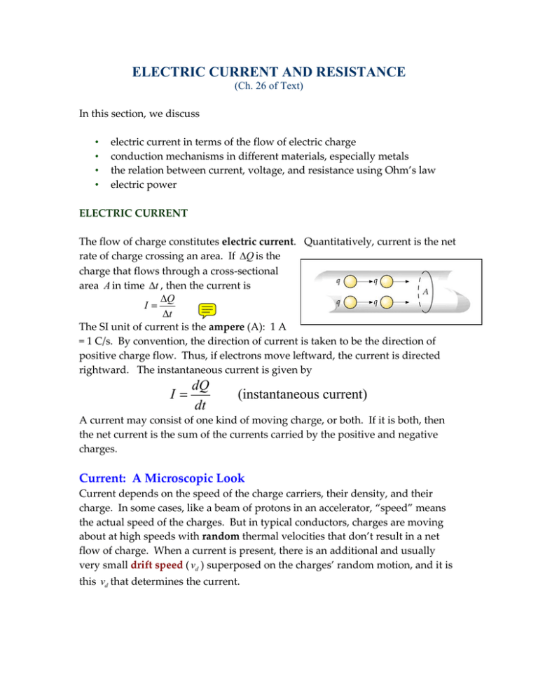
ELECTRIC CURRENT AND RESISTANCE (Ch. 26 of Text) In this section, we discuss • electric current in terms of the flow of electric charge • conduction mechanisms in different materials, especially metals • the relation between current, voltage, and resistance using Ohm’s law • electric power ELECTRIC CURRENT The flow of charge constitutes electric current. Quantitatively, current is the net rate of charge crossing an area. If Q is the charge that flows through a cross‐sectional area A in time t , then the current is Q I t The SI unit of current is the ampere (A): 1 A = 1 C/s. By convention, the direction of current is taken to be the direction of positive charge flow. Thus, if electrons move leftward, the current is directed rightward. The instantaneous current is given by I dQ dt (instantaneous current) A current may consist of one kind of moving charge, or both. If it is both, then the net current is the sum of the currents carried by the positive and negative charges. Current: A Microscopic Look Current depends on the speed of the charge carriers, their density, and their charge. In some cases, like a beam of protons in an accelerator, “speed” means the actual speed of the charges. But in typical conductors, charges are moving about at high speeds with random thermal velocities that don’t result in a net flow of charge. When a current is present, there is an additional and usually very small drift speed ( vd ) superposed on the charges’ random motion, and it is this vd that determines the current. The figure shows conductor that contains n charges per unit volume (units: C/m3), each with charge q and drift speed vd . Let A be the conductor’s cross sectional area. Consider a length L of the conductor: it has volume AL and contains nAL charge carriers for a total charge of Q nALq . Moving at vd , this charge ( Q ) takes time t L / vd to pass a given point. Then the current is Q nALq I nAqvd t L / vd Example: A copper wire has a radius of 0.815 mm. Assuming a number density of n 8.5 1028 / m3 , calculate the drift speed for a current of 1 A. Solution: Use the formula above with q e and A r 2 . I I 3.5 105 m/s 0.035 mm/s. vd neA ne( r 2 ) This is an extremely low speed! Estimate how long it takes for one of these drifting electrons to move one metre. Example: In a certain particle accelerator, a current of 0.5 mA is carried by a 5‐ MeV proton beam that has a radius of 1.5 mm. (a) Find the number density of protons in the beam. (b) If the beam hits a target, how many proton hit in 2 s? Solution: (a) Use n I / qAv with q e 1.6 1019 C and A r 2 . Find v from the KE. (Recall that 1 eV 1.6 1019 J .) K 1 2 2K 3.1107 m/s mv (5 106 ) (1.6 1019 ) J 8 1013 J v 2 m where m 1.67 1027 kg was used. Plugging in this value of v in n I / qAv , you'll find n 1.4 1913 protons /m3. (b) The total charge that strikes the target in 2 s is Q I t (0.5 103 C/s)(2 s) 1 mC. To find N , the number of protons hitting the target, divide Q by e : 103 C Q N 6.3 1015. 19 e 1.6 10 C Current Density: Currents aren’t confined to wires. Currents in the Earth, in chemical solutions, in your body, and in ionized gases flow in ill‐defined paths, and their magnitude and direction can vary with position. To characterize such diffuse currents, it is convenient to introduce current density, J , a vector whose direction at each point is that of the local current and whose magnitude is the current per unit area (units: A/m2). I nAqvd nqvd J nqvd J A A Conduction mechanisms: • Conduction occurs differently in different types of materials: • • • • • In metallic conductors, current is carried by free electrons. In ionic solutions, current is carried by positive and negative ions. Plasmas are ionized gases, with current carried by electrons and ions. Semiconductors involve current carried by both electrons and “holes”—absences of electrons in a crystal structure. • Semiconductors are at the heart of modern electronics. • Their electrical properties can be altered by the controlled addition of small amounts of impurities. Superconductors offer zero resistance to the flow of current, and thus can transmit electric power without loss of energy. • Known superconducting materials all require temperatures far below typical ambient temperatures. Resistance and Ohm's Law Electric fields exert forces on charges, so it is the presence of electric fields in conductors that results in a current. In a conductor in equilibrium, there is no electric field. When a potential difference is applied across a conductor, then an electric field is produced inside the conductor, and it is no longer in equilibrium. Newton’s law suggests that an electric field should accelerate free charges in a conductor, resulting in an ever‐increasing current. But in most conductors, charges collide with things—usually ions—and lose the energy they’ve gained from the field, as shown on the right. These collisions provide an effective force that counters the electric force, and the end result is that it takes an electric field to sustain a steady current. In many materials, the field and the current density are related by Ohm’s Law: J E (Ohms law, microscopic version) where is known as the conductivity of the material. We’ll restrict our attention to ohmic materials in which is independent of the applied field. (You may be more familiar with the macroscopic version of Ohm’s law, V IR , which we’ll discuss shortly.) The conductivity, , tells us how large a current density will result from a given field: it is a measure of how easily charges in the material can move. A perfect conductor would have ; a perfect insulator, 0 . A related quantity is the resistivity, , defined as the inverse of conductivity: 1/ . Then, Ohmʹs law, J E , can be written as J E . Resistance: The figure shows a wire segment of length L and cross‐ sectional area A carrying a current I . The field points in the direction of decreasing potential, so Va Vb . The potential difference is V Va Vb E L . The ratio V / I is defined to be the resistance of the segment: V (Resistance) I The SI unit of resistance is the ohm ( ): 1 1 Volt/Ampere. For many materials, R doesnʹt depend on the voltage drop or the current. Such materials, which include most metals, are called ohmic materials (mentioned earlier): V IR, ( R constant ) This is the macroscopic version of Ohmʹs law. The microscopic version is J E / . To see their equivalence, set V EL JL IL / A in V IR : Then, IL V IR L R. A A Thus, the two versions are equivalent if R L / A . R Example: A Nichrome wire ( 106 m) has a radius of 0.65 mm. What length of wire is needed to obtain a resistance of 2.0 ? Solution: Solve R L / A for L . Since A r 2 , 2 L ( r ) R 2.65 m. Example, A material has resistivity, a block of the material has a resistance: Problem 26.65 (from Ch 26 of Text): A potential difference V is applied to a wire of length L . cross-sectional area A , and resistivity . You want to change the applied potential difference and stretch the wire so that the energy dissipation rate is multiplied by 30.0 and the current is multiplied by 4.00. Assuming the wire's density does not change, what are (a) the ratio of the new length to L and (b) the ratio of the new crosssectional area to A ? Solution: We use P = i2 R = i2L/A, or L/A = P/i2. (a) The new values of L and A satisfy FG L IJ H AK new FG P IJ H i K 2 new FG IJ H K 30 P 42 i 2 old 30 16 FG L IJ H AK . old Consequently, (L/A)new = 1.875(L/A)old, and Lnew 1.875 Lold 1.37 Lold Lnew 1.37 . Lold (b) Similarly, we note that (LA)new = (LA)old, and Anew 1/1.875 Aold 0.730 Aold Anew 0.730 . Aold Ohm’s law: Comparing microscopic and macroscopic versions 26.4: Resistance and Resistivity, Variation with Temperature: Resistivity and resistance vary with temperature. Experimentally, it is found that the relation between temperature and resistivity for copper—and for metals in general—is fairly linear over a rather broad temperature range. For such linear relations we can write an empirical approximation that is good enough for most engineering purposes: (T ) 0 1 (T T0 ) Here, 0 is the resistivity value at a reference temperature T0 , usually taken to be 293 K (room temperature). is known as the temperature coefficient of resistance. The table on last page lists the values of and for some materials. Multiplying both sides of the above equation by L / A and recognizing R L / A , we find a similar relation is obeyed by the resistance: R(T ) R0 1 (T T0 ) For metals, and R increase with temperature, but for semiconductors, and R decrease. (The reason is the conduction mechanism in the two systems are quite different.) Problem 26.71 (from Ch 26 of Text): (a) At what temperature would the resistance of a copper conductor be double its resistance at 20.0°C? (Use 20.0°C as the reference point in Eq. 26.17; compare your answer with Fig. 26.10.) (b) Does this same “doubling temperature” hold for all copper conductors, regardless of shape or size? Solution: Solve R (T ) R0 1 (T T0 ) 2 R0 for T . We find (T T0 ) 1 . T T0 1 1 4.3 103 K 1 T 250 C (b) Yes, it holds for all Cu conductors, since they have the same . Power in Electric Circuits When there is an electric field in a conductor, the free electrons are accelerated for a short time, giving the electron gas increased KE, but this additional energy is quickly dissipated as thermal energy because of collisions with lattice ions. This increase in thermal energy is called Joule heat. The figure shows a segment of length L and area A carrying a current I . In time t , a charge Q enters from the left (at potential V1 ) and exits from the right (at potential V2 ). Let V V1 V2 . The change (decrease) in the PE of Q is U Q(V2 V1 ) Q(V ) V Q. The rate of energy loss is the time derivative: dU dQ V VI Power P VI . dt dt P VI is the rate at which Joule heat is produced in the conductor. Using V IR (Ohm's law), we may write this in other forms: V2 Power dissipated in a resistor P VI I R R 2 Example: The units of power are WATTS. Note that 1 W = 1 Volt.Ampere. Problem 26.45 (from Ch 26 of Text): A 1250 W radiant heater is constructed to operate at 115 V. (a) What is the current in the heater when the unit is operating? (b) What is the resistance of the heating coil? (c) How much thermal energy is produced in 1.0 h? Worked Solution THINK Let P be the power dissipated, i the current in the heater, and V the potential difference across the heater. The three quantities are related by P iV . EXPRESS The current is given by i P / V . Using Ohm's law V iR , the resistance of the heater can be written as R V V V2 . i P /V P ANALYZE a. Substituting the values given, we have b. Similarly, the resistance is c. The thermal energy E generated by the heater in time t 1.0 h 3600 s is LEARN Current in the heater produces a transfer of mechanical energy to thermal energy, with a rate of the transfer equal to P Vi V 2 / R . EMF and Batteries To maintain a current in a conductor, we need a supply of electrical energy. A device that supplies electrical energy is called a source of emf. (The letters emf stand for electromotive force, a term that is now rarely used.) Examples of emf sources are a battery (which converts chemical energy into electrical energy) and a generator (which converts mechanical energy into electrical energy). A source of emf does work on a positive charge passing through it, raising its PE. The work done on unit charge is called the emf, , of the source. The unit of is the volt. An ideal battery is a source that maintains a constant potential difference (PD) between its terminals, independent of the current flow. The figure shows a simple circuit consisting of an ideal emf and a resistor. Assuming connecting wires to have negligible resistance, we find Va Vb Vc Vd . The current is clockwise and has the value I / R by Ohm's law. Consider a charge Q moving through the emf (from ‐ to +) in a time t . Its gain in PE is Q . The rate at which PE is gained is the power output of the emf: Q P I t As the charge flows through R , this PE is converted into thermal energy: the power output of the source equals the power dissipated in R (energy conservation). In a real battery, the PD across the battery terminals (called the terminal voltage) depends on the current flowing, as the graph shows. In the circuit on the right, the battery is real and has an internal resistance r . The terminal voltage is not any more; it is now Va Vb Ir . This obviously decreases linearly with the current. Since the connecting wires have no resistance, Va Vb Ir IR , which can be solved for the current: I ( R r ) . In the previous case, we assumed r 0 , and so I voltage was Va R and the terminal Vb IR . Real batteries such as a good car battery usually have an internal resistance of the order of a few hundredths of an ohm, so the effect of the Ir term is negligible unless the current is very large. One sign of a bad battery is large of value of r . If you suspect your car battery is bad, checking the terminal voltage with a voltmeter (which draws only a small current) is not sufficient: you need to check it while a large current is drawn from the battery, such as while you are starting your car. Car batteries are often rated in ampere‐hours (A.h), which is the total charge they can deliver: 1 A.h = (1 C/s)(3600 s) = 3600 C. The total energy stored in the battery is W Q . Example: An 11 resistor is connected across a battery of emf 6 V and internal resistance 1 . Find (a) the current, (b) the terminal voltage, (c) the power delivered by the battery, (d) the power delivered to the 11 resistor, and (e) the power dissipated by the batteryʹs internal resistance. (f) If the battery is rated at 150 A.h, how much energy does it store? Solution: (a) I (b) Va (R r) 6 (11 1) 0.5 A. Vb Ir 6 (0.5)(1) 5.5 V. (c) Pbat (d) I 3 W. PR I 2 R 2.75 W. (e) Power dissipated as heat inside the battery is I 2 r 0.25 W. This is equal to Pbat PR , which is not surprising (energy conservation). (f) The total energy stored is the emf times the total charge: C W Q (150A.h ) 3600 6 V 3.24 MJ. 1h


