COMBINATIONS OF CAPACITORS 26.3
advertisement

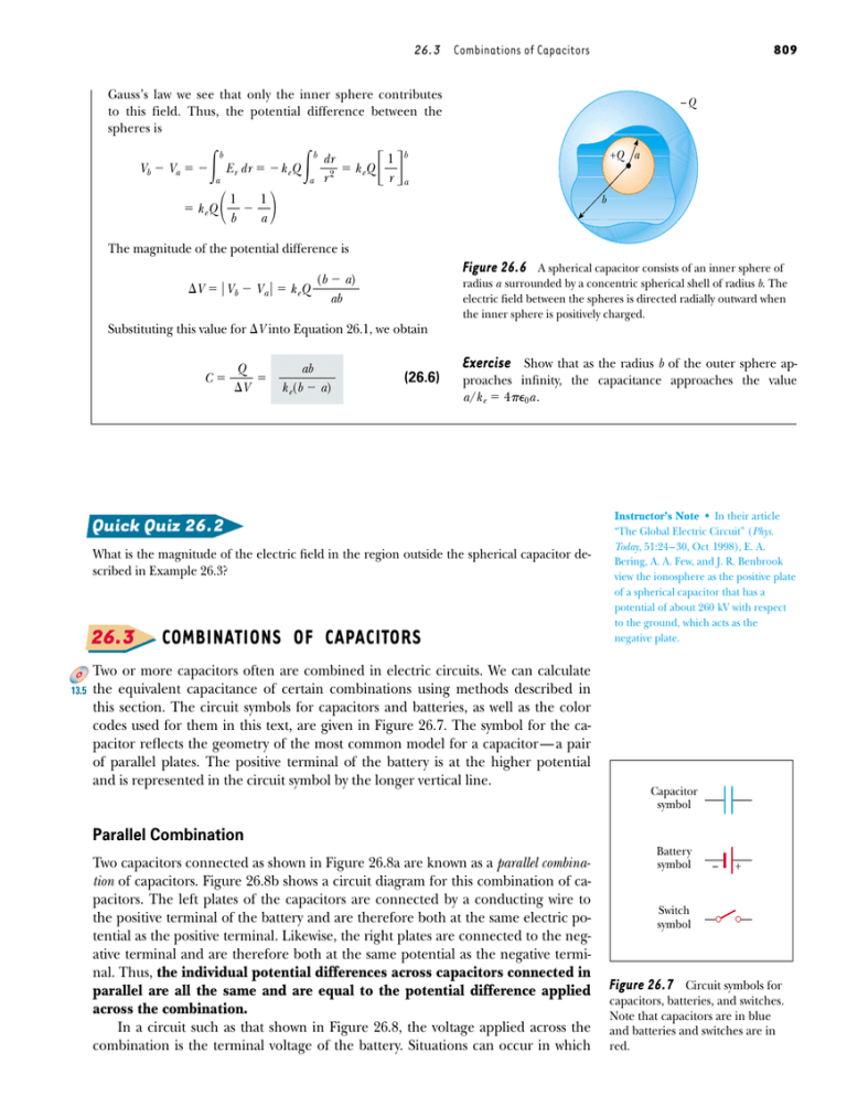
26.3 Combinations of Capacitors 809 Gauss’s law we see that only the inner sphere contributes to this field. Thus, the potential difference between the spheres is Vb Va b a k eQ E r dr k e Q 1 1 b a b a dr k eQ r2 –Q 1 r +Q a b a b The magnitude of the potential difference is (b a) V V b V a k e Q ab Substituting this value for V into Equation 26.1, we obtain C Q V ab k e(b a) Figure 26.6 A spherical capacitor consists of an inner sphere of radius a surrounded by a concentric spherical shell of radius b. The electric field between the spheres is directed radially outward when the inner sphere is positively charged. Exercise (26.6) Show that as the radius b of the outer sphere approaches infinity, the capacitance approaches the value a/k e 40a . Quick Quiz 26.2 What is the magnitude of the electric field in the region outside the spherical capacitor described in Example 26.3? 26.3 13.5 COMBINATIONS OF CAPACITORS Two or more capacitors often are combined in electric circuits. We can calculate the equivalent capacitance of certain combinations using methods described in this section. The circuit symbols for capacitors and batteries, as well as the color codes used for them in this text, are given in Figure 26.7. The symbol for the capacitor reflects the geometry of the most common model for a capacitor — a pair of parallel plates. The positive terminal of the battery is at the higher potential and is represented in the circuit symbol by the longer vertical line. Instructor’s Note • In their article “The Global Electric Circuit” (Phys. Today, 51:24 – 30, Oct 1998), E. A. Bering, A. A. Few, and J. R. Benbrook view the ionosphere as the positive plate of a spherical capacitor that has a potential of about 260 kV with respect to the ground, which acts as the negative plate. Capacitor symbol Parallel Combination Two capacitors connected as shown in Figure 26.8a are known as a parallel combination of capacitors. Figure 26.8b shows a circuit diagram for this combination of capacitors. The left plates of the capacitors are connected by a conducting wire to the positive terminal of the battery and are therefore both at the same electric potential as the positive terminal. Likewise, the right plates are connected to the negative terminal and are therefore both at the same potential as the negative terminal. Thus, the individual potential differences across capacitors connected in parallel are all the same and are equal to the potential difference applied across the combination. In a circuit such as that shown in Figure 26.8, the voltage applied across the combination is the terminal voltage of the battery. Situations can occur in which Battery symbol – + Switch symbol Figure 26.7 Circuit symbols for capacitors, batteries, and switches. Note that capacitors are in blue and batteries and switches are in red.


