Manual
advertisement

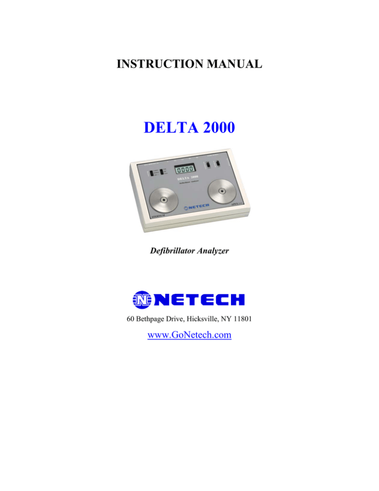
INSTRUCTION MANUAL DELTA 2000 Defibrillator Analyzer 60 Bethpage Drive, Hicksville, NY 11801 www.GoNetech.com TABLE OF CONTENTS General Information 2 Product Description 3 Operating Instructions 5 Theory of Operation 9 Specifications 11 Test and Calibration. 12 Safety Considerations Defibrillators deliver high voltage shocks to a patient in order to stop a heart attack. The Defibrillator discharge pulse is potentially dangerous. Before attempting to use Delta2000 get thoroughly familiar with the defibrillator under test and follow the manufacturer’s safety protocols. GENERAL INFORMATON Introduction Delta 2000 is intended to operate only by qualified technical personnel. Before attempting to use DELTA 2000 please observe the safety procedures for safe handling of the unit and also to avoid potential shock hazard. The operator must be familiar with the unit and follow the safety precautions listed below. Refer to the Defibrillator manufactures operating manual for additional safety considerations. Defibrillators deliver high voltage shocks to a patient in order to stop heart attack. Defibrillator pulse is potentially dangerous. Safety Considerations If any fluid is spilled on the unit or the unit is dropped, do not use until thoroughly tested. Do not touch the metal surface of the paddle. Place DELTA 2000 onto a flat firm surface before discharging the defibrillator. Apply both paddles firmly centered on the discharge plates of DELTA 2000. If the paddles are not firm arcing may occur. Arcing can cause injury to the operator and damage the unit. Do not touch the contact plates when defibrillator paddles are placed on the plates. Do not use any gel, pads or conductive material on the paddles when testing on the DELTA 2000. Use only the recommended paddle adapters for testing the Automated External Defibrillators. PRODUCT DESCRIPTION Introduction DELTA 200 is a compact, state of the art defibrillator analyzer designed for testing the performance of Defibrillators including the AEDs (Automated external Defibrillators). Features The four performance characteristics of a defibrillator are discharge energy, synchronized mode operation, automated external defibrillator (AED) function and ECG monitoring. The DELTA 2000 is specifically intended to test all four parameters. It measures the output energy and cardioversion delay time in synchronized mode. The internal 50 Ohms load simulates the human body. The DELTA 2000 simulates several test waveforms. The simulated waveforms, ECG, VTAC, VFIB and NSR (Normal Sinus Rhythm @ 90BPM) are output through the paddles for testing the Automated External Defibrillators (AED). Additional arrhythmia waveforms can be input into DELTA 2000 through the phone jack input for interactive training purposes. Discharge waveform is stored in the memory. The time expanded discharge waveform is played back through the paddles and ECG leads. Real time discharge waveform is output through the output phone jack for observing on a scope. Product Familiarity 4 2 5 7 8 6 3 9 10 1 11 5 2 7 10 (1) (2) Mode Selector ECG High Level Output, Arrhythmia Input Jack (3) AED waveform selector (4) Battery Compartment (5) ECG Leads Output 4 (6) (7) (8) (9) (10) (11) Display Scope Output Jack Energy range Selector On/OFF Switch DC Jack Defibrillator paddle Contacts OPERATING INSTRUCTIONS Setup Although DELTA 2000 is simple to operate and requires minimum setup, the user must read the manual thoroughly for safe and proper operation. The DELTA 2000 operates with a 9 Volt Alkaline Battery or optional AC adapter (Netech Part # 302). The unit is shipped with a fresh battery. To replace the battery open the battery compartment located below the ECG leads in the rear of the unit. If using the AC adapter, plug the unit into the Jack on the right side of the unit. Use only the recommended AC adapter. DELTA 2000 uses a large four-digit LCD display and four slide switches located on both side of the display. Two of the slide switches (left) are three position and the two (right) are two positions. DELTA 2000 provides three modes of operation, selectable by the ‘MODE’ switch. When the ‘MODE” switch is in CARDO position the display flashes ‘-000’ and the ECG waveform is output to through the paddle and ECG leads. DELTA 2000 is now ready to measure the cardio-version delay time. In ENERGY Mode the display flashes ‘0000’ or ’00.00’ depending on the ‘ENERGY’ Range selector switch in HIGH or LOW. The unit is now ready to measure the energy discharged into the circular metal plates marked STERNUM and APEX. The AED MODE selector simplifies the testing of the AEDs. In this MODE the DELTA 2000 simulates VFIB NSR or VTAC depending on the waveform selector. Energy Measurement Defibrillator discharge voltages are potentially dangerous. Before attempting to test the Defibrillator please observe the necessary safety procedures for the safe handling of the unit and also to avoid potential shock hazard. Place DELTA 2000 on a flat non-skid flat surface close to the Defibrillator under test. Turn the unit by flipping the ON/OFF switch to ON. Select the MODE switch to ENERGY (middle Position). The display flashes ‘0000’ or ’00.00’ depending on the position of the energy range selector. Select the range corresponds to the Defibrillator energy to be measured. For energy values below 100 select LOW. Place the Defibrillator paddles firmly against the circular plates on DELTA 2000 and charge the Defibrillator to the desired energy level. Ensure all the safety precautions. Discharge the defibrillator. The delivered energy reading will be displayed until the next discharge/test. Note: In LOW range if the discharged energy is greater than 99.99 Joules, then the display flashes HI continuously. In this case change the range selector to HI and discharge the Defibrillator a second time. In Hi range if the discharge energy exceeds 700 the display flashes ‘HELP’ continuously. CAUTION DO NOT USE ELECTRODE PASTE ON PADDLE CONTACTS. DO NOT DISCHARGE DEFIBRILLATOR IN THE PRESENCE OF FLAMMABLE ANESTHETICS. Waveform Recording While the Defibrillator is discharged onto DELTA 2000 the captured waveform will be continuously output through the ECG leads, paddle contacts, and high level output jack marked ‘ECG/ARTH OUT/IN) located on the left side of the rear panel of DELTA 2000. This waveform is amplitude scaled to provide maximum output and time scaled to provide a time expansion of 1:200. The same waveform is repeated at 8 seconds intervals. If the Monitor/Recorder associated with the Defibrillator can sense through the paddles, the waveform from DELTA 2000 will be automatically captured by the Monitor Recorder, as long as the Defibrillator paddles are in contact with the DELTA circular plates. If there is no paddle sensing capability (older units), then ECG leads must be connected to the ECG input leads on the Monitor/Recorder. Real time Scope Output The attenuated Defibrillator discharge waveform can be observed on an oscilloscope. Connect an oscilloscope to the phone jack marked ‘Scope Output’ on the right side of the rear panel of DELTA 2000. Set the sweep to 1ms/div and vertical gain to 1 Volt. Discharge the Defibrillator onto the paddle contacts on DELTA 2000 and observe the waveform. The amplitude reduction is 1000:1 Volt. (The output is 1V/1000V). Cardioversion Testing Set the MODE switch to CARDIO. The display flashes ‘-000’ and a simulated ECG waveform @ 60 BPM is output through the ECG leads and the paddle contacts. Connect the ECG leads of the Defibrillator monitor. Set the Defibrillator to synchronize mode. Select the source of the ECG to leads. Discharge the Defibrillator into the paddle contacts. DELTA 2000 measures the time delay between the peak of the R wave of the ECG and the rising edge of the Defibrillator discharge waveform. The reading is displayed in Milliseconds. Measured time is positive if the leading edge of the discharge waveform occurs after the peak of the R wave (on the negative slope of the QRS of the ECG). If the discharge occurs on the positive slope of QRS) ‘-‘ sign will be displayed, indicating negative reading. If the reading exceeds the range (+/-250), the display flashes ‘OOPS’. Testing Semi/Fully Automatic Defibrillators Refer to the Defibrillator manufactures service manual for specific device inspection requirements. Observe the safety precautions. For Fully automated Defibrillators use the correct paddle adapter for the Defibrillator under test. The paddle contact plate must not be exposed during discharge. Set the MODE switch on the DELTA 2000 to AED. Select the desired waveform for the advisory shock feature of the Defibrillator. Select the ENERGY range switch to the desired range. Connect the paddle adapter to the circular contact plate (for fully automated Defibrillator) or place the paddle firmly on to the paddle contact (semi automatic Defibrillator) and discharge. The DELTA 2000 displays the measured energy. A unique feature of the DELTA 2000 is the capability to input any desired waveform required to activate the automated Defibrillator into the unit by connecting an arrhythmia simulator ( Netech’s MiniSim 1000 ) to the ‘ECG/ARTH OUT/IN jack. Set the MODE switch to ENERGY. Select the manufactures recommended waveform from the arrhythmia simulator. THEORY OF OPERATION Introduction The DELTA 2000 is a precision micro controller based device that performs tests on automated and semi automated Defibrillators. This instrument utilizes modern analog to digital converter techniques to capture the Defibrillator discharge waveform. Switches Amp and A/D Input Load 50 Ohms And Attenuator Micro controller Memory Output D/A Converter Display DELTA 2000 Circuit Block Diagram Description DELTA 2000 circuitry is divided into eight functional blocks for the purpose of simplicity. The input load and attenuator block consists of the precision 50 Ohm high watt resistor and attenuation resistors. The discharged waveform is attenuated and buffered and fed to a 13 Bit (12 Bit + sign bit) A/D converter interfaced with an 8 bit Microcontroller, Philips P80C52. The waveform is sensed by the A/D and sampled at a rate of 1000 times per second and saved in the memory. The captured waveform is time scaled to 1:200 and dumped into a 12-bit D/A converter. The stored waveform can be observed through the paddle and the ECG Leads. In ENERGY mode the micro controller computes the energy content of the captured waveform and displays the result on the display. During cardioversion the micro controller produces an ECG waveform @ 60 BPM through the D/A converter and wait for the discharge waveform. The time between the rising edge of the discharge waveform and the peak R wave of the simulated ECG is measured and displays in milli seconds on the display. If the discharge occurs on the negative slope a negative sign also displayed. The waveform is also stored in the memory and when the MODE switch is changed to energy the micro controller calculated the energy and displays. The accuracy of the DELTA 2000 is maintained by a precision calibrated voltage source, a crystal oscillator running at 11.0592 MHz and a set of 0.1% load resistors and attenuation resistors. The unit is factory calibrated with N. I. S. T traceable standards. In order to ensure the specified accuracy, factory recalibration is recommended on an annual basis. SPECIFICATIONS Internal Test load: 50 Ohms +/- 1% Pulse Width: 1- 65 ms Energy Range: Resolution: Accuracy: Low: 0 – 99.99 Joules High: 0 – 700 Joules Low Range: 0.01 Joule High Range: 1 Joule Low Range +/- 2 % Rdg. +/- .1Joule High Range +/- 2% Rdg +/- 2 Joules Cardioversion Delay: +/- 250 Milli Seconds from Peak R Accuracy: +/- 1% of full scale +/- 1 ms Waveform Simulation: Internal: ECG @ 60 BPM VTAC, VFIB & NSR @ 90 BPM External: Waveform input through Input Jack. Discharge Waveform: Real time: Voltage attenuation 1000:1 Expanded time: 1:200 repeated every 8 seconds. Display: 4 Digit Large LCD disply. Power: 9 V alkaline battery or AC adapter. Weight: 3 lb (1.6 Kg) Dimensions: 10.4 x 7.2 x 4.0”(26.4x18.2x10.2cm) Optional Adaptors: Paddle adapter sets are available for most AEDs. Call Netech for part #. TEST AND CALIBRATION Introduction Before attempting to test the unit please observe the necessary safety precautions for safe handling of the unit and also to avoid potential shock hazard. The operator must be familiar with the unit and follow the safety precautions listed in the ‘Safety precautions’ in the General Information section of this manual. Performance Check This check is recommended upon the initial receipt of the unit. Before proceeding with the test inspect the instrument thoroughly to ensure that no visual damage caused during transportation/shipping. The DELTA 2000 is shipped with a 9 Volt Alkaline battery. Turn the unit on by flipping the Power ON/OFF to ‘ON’. If the battery voltage is below 6.8Volt, display indicates, ‘LOP’. Turn unit off and replace the battery. Connect the ECG leads of the Defibrillator Monitor to the ECG output jack (ECG snap/banana adapter is provided). Select the ECG source of the Monitor/Defibrillator to ECG leads. Set the MODE switch to Cardio. The display flashes ‘-000’ and ECG waveform @ 60 BPM will appear on the monitor. Place the paddles on the paddle contacts. ECG waveform should appear when source selected to paddle. Calibration DELTA 2000 is factory calibrated and thoroughly tested and found to meet the Netech’s manufacturing specifications before being shipped. Calibration measurement standards are traceable to the National Institute of Standards and Technology (NIST). Any attempt to tamper with the calibration seal will void the warranty.

