2.5Gbps Laser Diode Driver
ments, fast product turn-around time dominates
the customer’s decision-making process in vendor
selection. The exponential growth in optical technology due to this high bandwidth demand, along
with competition in optical components, makes
customers more demanding and specific about
product requirements.
High-Bandwidth Demand
The increasing demand for high-bandwidth in
different applications related to the Internet,
telecommunications, data communications, fiber
channel, etc., has created a tremendous need for
fiber rich networks and the components that support them. To meet these high bandwidth requireSony
Optical Fiber
Pre-Amp
Post-Amp
Photo
Diode
CDR
DeMux
Phase
Modulation
Switch
Fabric
Sony
Optical Fiber
Laser
Diode
Laser
Diode
Driver
Multiplexer Convert
Phase
Modulation
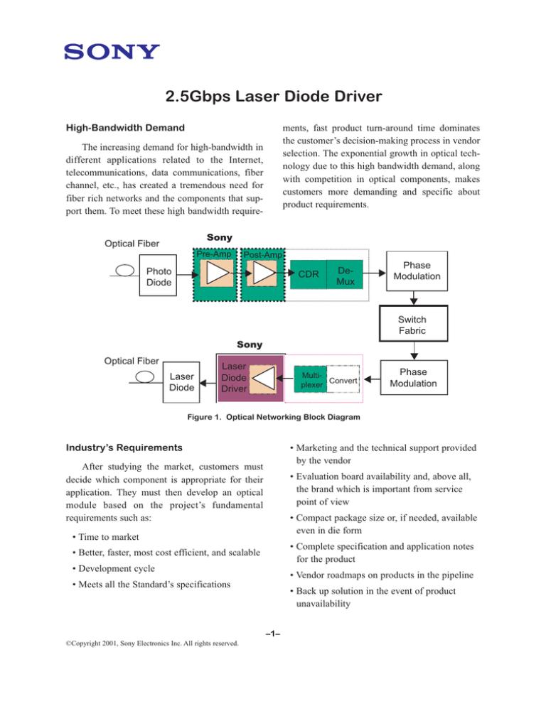
Figure 1. Optical Networking Block Diagram
Industry’s Requirements
• Marketing and the technical support provided
by the vendor
After studying the market, customers must
decide which component is appropriate for their
application. They must then develop an optical
module based on the project’s fundamental
requirements such as:
• Evaluation board availability and, above all,
the brand which is important from service
point of view
• Compact package size or, if needed, available
even in die form
• Time to market
• Complete specification and application notes
for the product
• Better, faster, most cost efficient, and scalable
• Development cycle
• Vendor roadmaps on products in the pipeline
• Meets all the Standard’s specifications
• Back up solution in the event of product
unavailability
–1–
©Copyright 2001, Sony Electronics Inc. All rights reserved.
Qualifying Tests
About Sony’s Laser Diode Driver
Qualification of these devices is time consuming. The customer needs to perform multiple tests,
including:
The CXB18128 is a single high-speed monolithic Laser Diode Driver with positive referenced
emitter coupled logic (PECL) and current mode
logic (CML) input level.
• Electro-optical test, requiring several weeks
CXB1828 has built-in Automatic Power
Control Circuitry (APC) for bias current and a
Signal Duty Correction Circuit. The key function
for this device is to provide the bias output current
and the modulation output current, which is
between 3mA and 50mA. It is available in a compact package and also in a wafer form. The overall characteristics make the Laser Diode Driver
better, faster, more cost efficient and scalable.
Typical applications include fiber optics-based
communications and Gigabit Ethernet.
• Life time tests, taking a few months
• Fulfillment of all standards (ITU / Bellcore)
specifications
• Check AC / DC characteristics and power consumption
• Confirm vendor-provided temperature characteristics and package qualification
Why Sony’s Laser Diode Driver
Sony has a line of optical communication
products and a promising road map including
10Gbps follow-on products. Based on the criteria
and concerns already mentioned, one of these
high-performance optical networking products is
the Laser Diode Driver (LDD). An ideal product
for fiber optics applications, CXB1828 high speed
LDD with Automatic Power Control (APC) is part
of Sony’s family of 2.5 Gbps optical networking
ICs for use in high-performance optical transmitter and receiver functions. The CXB1828 possesses design flexibility while meeting the need for
high performance, reliability, and low cost. It
comes in a compact 32pin VQFN plastic package
with a fine lead pitch of 0.4mm and is proven in
fiber optics applications. A typical SONET application fully utilizing this product is an OC-48
module, producing a data rate of 2.488 Gbps.
The CXB1828 is a complete 2.448Gbps laser
diode driver powered with single +3.3V supply
and the control of the diode bias current is
achieved through the automatic power control circuitry. An APC circuit is provided to maintain
constant laser power in transmitters that use a
monitor photodiode.
The CXB1828 accepts differential PECL and
CML data inputs and provides output currents.
PECL is input to the data buffer at a maximum
data rate. The shutdown and input alarm circuit
disables both the modulation current driver and
laser diode bias generator under various conditions. The shutdown has TTL input to disable output current. This chip also provides an on-chip
input termination of 50 Ohms.
–2–
Features
Application
• Directly drives laser diode
Typical applications for the LDD are:
• Low cost IC fabricated in bipolar process
• Maximum data rate of 2.5Gbps
• SONET /SDH transmission systems and
modules
• Power on Reset function
• OC-48 fiber optic modules
• Automatic Power Control (APC) for bias
control
• SONET/SDH: 622Mbps, 2.5Gbps
• Gigabit Ethernet: 1.25Gbps
• Built in Shutdown, Input Alarm and Reset
circuitry
• Acceptable PECL and CML inputs
• Internal duty cycle correction circuit
• Activity error detector function
• Typical rise time is 100ps
• Low power consumption of 48mA
• Available in both in wafer form or in 32 pin
VQFN package
• On-chip input termination
• Compact package size of 4.8mm X 4.8mm
• Industry standard interface
• Single +3.3V supply voltage
Laser
Diode
Laser Diode Driver
Multiplexer Convert
Phase
Modulation
Figure 2. Typical Transmitter Unit for SONET/SDH Fiber System
As fiber optics data communication products
are growing at a rapid pace, higher speed, compact sizes and increased functionality is imminent. Even though greater integration is possible
(though not desirable in all cases), this provides
the customer more room for flexibility.
Conclusions
Benefits
• Directly drives laser diode
• Low power consumption
• Internal duty cycle correction circuit
Embracing this growing market trend, Sony
will provide more integrated devices with highspeed optical components that reach up to
10Gbps. These devices will be available in wafer
form as well as traditional packaging. Sony’s
product roadmap potentially includes products
such as Post-Amp, Laser Diode Driver (LDD),
Clock & Data Recovery (CDR), SERDES and
Pre-Amp.
• Built in Shutdown, Input Alarm and Reset circuitry
• TTL / PECL/ CML Inputs acceptable
• Compact package size 4.8mm x 4.8mm
–4–


