Product Datasheet
April 2011
Provers
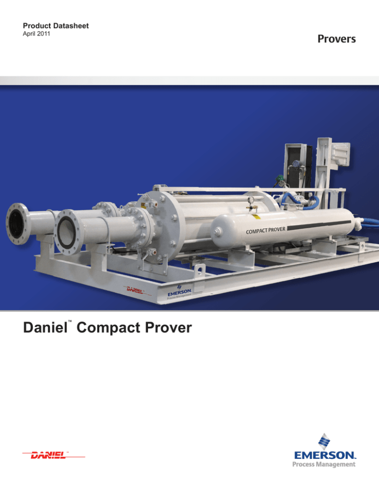
Daniel Compact Prover
®
Daniel Compact Prover
™
TM
Product Datasheet
April 2011
Daniel Compact Prover
™
Daniel Compact Prover provides high accuracy, rapid
operation and continuous flow for proving a flow meter
in an operational line. This is accomplished without
interrupting normal flow and without the use of manually
operated bypass valves.
Its unique design features a piston assembly with an
internal poppet valve in conjunction with optical position
sensing, hydraulic piston return, pneumatic piston
actuation and modern data processing techniques. The
result is a complete packaged proving system significantly
reduced in size, weight and cost while equalling or
exceeding the performance of conventional provers.
Features and Benefits
• Compact and portable – a single prover may be used in
multiple locations for proving various sizes of meters
• 1000:1 flow rangeability
• Skid or trailer mounted
• Vertical mounting available for applications having
space constraints
• Rapid proving operation offers single or multi-pass • Versatility – operates with virtually any pulse output operation with immediate K-factor calculation
flow meter
Daniel Compact Prover offers flexible mounting
configurations on a truck or trailer for field proving of flow
meters, or can be permanently installed in a testing facility
either vertically or horizontally.
• Positive leak checking
• Automatic mechanical operation assures undisturbed
Pulse interpolation electronics permit exact time
determination and pulse counting which provides high
accuracy proving with a smaller volume and fewer flow
meter pulses than any previous prover technology. The
use of a small displacement volume is made possible by
the high resolution of Daniel Compact Prover which is
attributed to two major factors; precision optical switches,
and data acquisition using double chronometry.
Application Range
Optical switches are used for defining prover volume by
detecting the piston position. These switches are reliable,
precise and have a fast response time (5 x 10⁻⁶ seconds).
Data acquisition, using double chronometry, allows a
much higher degree of meter pulse resolution than the
±1 pulse common to conventional pipe provers.
Control and operation of Daniel Compact Prover is
accomplished by a microprocessor based device providing
the advanced electronic capabilities necessary for control
in proving volumetric or mass meters.
Daniel Compact Prover conforms to design guidelines
prescribed in API Chapter 4.2 and Pulse Interpolation
techniques in API Chapter 4.6. All proving report formats
have been designed in accordance with API standard,
Chapter 12 Calculation of Petroleum Quantities of the
“Manual of Petroleum Measurement”.
product flow
• Corrosion resistant flow tube
• Flexibility-volumetric or mass meter proving
•
•
•
•
Typical Fluids
Crude Oil
Light Refined Product
Refined Product
Compact Prover Range
• Flow Rate: 0.25 to 17,500 gpm (0.357 bph to 25,000 bph)
• Temperature*: -46º F to 500º F
(- 43º C to 260º C)
• Pressure: 150 to 1,500 ANSI Class
*Subject to material specifications.
Daniel™ Compact Prover is formerly known as the Brooks® Compact Prover™.
Page 1
Product Datasheet
April 2011
Specifications
Please consult the factory if your requirements are outside the specifications noted here. Improved performance and
other product and material offerings may be available depending on the application.
Performance
Repeatability: 0.02% or better (water draw)
Pressure Drop
• Piston only: Approximately 1” of water during Color is light grey as standard top coat, white available by request.
prover pass
• Maximum flow: Approximately 10 psig across Paint
• 2 Coat system: Epoxy primer/urethane
• 3 Coat system: Inorganic zinc/epoxy/urethane
• 4 Coat system: Inorganic zinc/epoxy (2 coats) urethane
inlet/outlet flanges (on water)
Standard Materials of Construction
• Flow Tube: 17- 4 PH Stainless steel
• Piping and Flange: Carbon steel
• Poppet Seal: Fluroelastomer (FKM)
• O-rings: Fluroelastomer (FKM)
Cable Specifications
• 1000 ft (305m) max for distance between flow computer and prover
NEC
IEC
Electric:
Sheathed
Armored
Control:
Sheathed
Armored
Pressure Ratings
ANSI RATINGS
PROVER SIZE
Available Mounting Configurations
• Horizontal
• Vertical
• Vertical Lift
• Mirror Image
Electrical Connections
• 1/2" / 1" NPT
• M20 / M32
150
300
600
900
1500
8"
CF
12" mini
CF
12"
CF
18"
CF
24"
CF
34"
CF
NA
NA
40"
CF
NA
NA
= Available
CF = Consult factory
NA = Not available
Pressure and Temperature: Smart pressure and temperature transmitters are used where applicable. (Rosemount® 3051 and 3144 Series)
Page 2
Product Datasheet
April 2011
Standard Compact Prover Capacities - Flow Rates, Dimensions and Weights:
NOMINAL
FLOW TUBE
DIAMETER
8"
12" MINI
12"
18"
24"
34"
40"
PROVER FLOW RATE
RANGES
MINIMUM
MAXIMUM
0.25 GPM
250 GPM
0.357 BPH
357 BPH
0.946 LPM
0.057 M3PH
1.0 GPM
1.43 BPH
3.78 LPM
946 LPM
57 M3PH
1,000 GPM
1,430 BPH
3,780 LPM
0.227 M3PH
227 M3PH
1.75 GPM
2.5 BPH
6.623 LPM
0.397 M3PH
3.5 GPM
5.0 BPH
13.247 LPM
0.794 M3PH
1750 GPM
2,500 BPH
6,623 LPM
397 M3PH
3,500 GPM
5,000 BPH
13,247 LPM
794 M3PH
7.0 GPM
7,000 GPM
10.0 BPH
26.583 LPM
1.595 M3PH
12.6 GPM
18.0 BPH
47.691 LPM
2.860 M3PH
17.5 GPM
25.0 BPH
66.237 LPM
10,000 BPH
26,583 LPM
1,595 M3PH
12,600 GPM
18,000 BPH
47,691 LPM
2,860 M3PH
17,500 GPM
25,000 BPH
66,237 LPM
3.972 M3PH
3,972 M3PH
NOMINAL
PROVER
BASE
VOLUME
INLET/
OUTLET
FLANGE SIZE
5 GAL
NOMINAL PROVER
SHIPPING DIMENSIONS
(L X W X H)
APPROX.
SHIPPING
WEIGHT
121" X 56" X 50"
2,200 LBS
307CM X 142CM X 127CM
998 KGS
147" X 62" X 55"
4,400 LBS
373CM X 157CM X 140 CM
1,995 KGS
172" X 67" X 57"
4,900 LBS
437CM X 170CM X 145CM
2,223 KGS
193" X 76" X 56"
7,300 LBS
490CM X 193CM X 142CM
3,311 KGS
220" X 96" X 66"
13,400 LBS
559CM X 244CM X 168CM
6,078 KGS
230" X 102" X 74"
19,200 LBS
584CM X 259CM X 188CM
8,709 KGS
240" X 130" X 77"
35,000 LBS
610CM X 330 CM X 196CM
13,876 KGS
2"
20 LITERS
10 GAL
4"
40 LITERS
15 GAL
6"
60 LITERS
30 GAL
8"
120 LITERS
65 GAL
12"
250 LITERS
100 GAL
16"
400 LITERS
170 GAL
20"
650 LITERS
NOTE: Please consult the factory for your compact prover configuration. Improved performance and other product and material offerings
may be available depending on the application.
Page 3
Product Datasheet
April 2011
Power Requirements
POWER REQUIREMENTS
SIZE
8" and 12"
mini
12"
18"
24"
34"
40"
AC LINE VOLTAGE/
FREQUENCY/PHASE
HYDRAULIC MOTOR FULL
LOAD AMPS
HYDRAULIC MOTOR
CONFIGURATION
HYDRAULIC
CONTROL VALVE
IN-RUSH AMPERAGE
AVAILABILITY
115/60/1
13.4
1 hp Single
10
AVAILABLE
220/50/1 & 230/60/1
6.7
1 hp Single
5
AVAILABLE
380/50/3
3.6
2.0 hp Single
NA
AVAILABLE
415/50/3
3.3
2.0 hp Single
NA
AVAILABLE
460/60/3
2.2
1.5 hp Single
5
AVAILABLE
115/60/1
19
1.5 hp Single
10
CONSULT
FACTORY
220/50/1 & 230/60/1
8.4
1.5 hp Single
5
AVAILABLE
380/50/3
3.6
2.0 hp Single
NA
AVAILABLE
415/50/3
3.3
2.0 hp Single
NA
AVAILABLE
460/60/3
2.2
1.5 hp Single
5
AVAILABLE
115/60/1
19 x 2
1.5 hp Dual
2 circuits
NA
CONSULT
FACTORY
220/50/1 & 230/60/1
19
1.5 hp Dual
1 circuit
NA
AVAILABLE
230/60/3
13
NA
AVAILABLE
380/50/3
9
415/50/3
8.3
NA
AVAILABLE
460/60/3
6.5
NA
AVAILABLE
690/50/3
5
NA
CONSULT
FACTORY
230/60/3
13
NA
AVAILABLE
380/50/3
9
415/50/3
8.3
NA
AVAILABLE
460/60/3
6.5
NA
AVAILABLE
690/50/3
5
NA
CONSULT
FACTORY
230/60/3
39
NA
AVAILABLE
380/50/3
22
415/50/3
20
NA
AVAILABLE
460/60/3
19.5
NA
AVAILABLE
690/50/3
12.8
NA
CONSULT
FACTORY
230/60/3
50
NA
380/50/3
28
CONSULT
FACTORY
NA
AVAILABLE
415/50/3
26
NA
AVAILABLE
460/60/3
25
NA
AVAILABLE
5 hp Single
5 hp Single
15 hp Single
20 hp Single
NA = Not available
Page 4
Product Datasheet
April 2011
Standard Factory Tests
• Hydrostatic: Chart recorded pressure test to 1.5 times
max working pressure
• Water draw: Calibration test within 0.02% repeatability
traceable to NIST
• Functional: Verifies functionality of prover, components
(i.e., instrumentation) and repeatability as per API
Chapter 4
Weights and Measures Approvals
• National Conference of Weights & Measures (NCWM)
• National Type Evaluation Programs (NTEP)
• Measurement Canada - Canada
• Nederlands Meetinstituut (NMi)
• Physikalisch-Technische Budesanstalt (PTB)
• Norwegian Weights and Measures
• Standards & Industrial Research Institute of Malaysia (SIRIM)
Hazardous Location Approvals
CE Mark for the European Community, including all applicable European directives and standards.
Ex de ia m IIB T3 (ATEX, PED)
Canadian Standards Association (CSA International) approval for hazardous locations, Class I, DIV. 1, Group D
Electrical systems conforming to National Electrical Code,
Class I, Div. 1, Group D or CSA Std C22.2, Class I, DIV. 1,
Group D, using UL/CSA approved components only
Weather Proofing
NEC
IEC
Enclosure:
NEMA4
IP66
Motors:
NEMA3
IP54
- optional NEMA3 IP66
• Gosstandart (GOST)
• Directorate General of Oil and Gas (Migas) - Indonesia
Page 5
Product Datasheet
April 2011
Engineered Proving Solutions
Daniel offers an engineered solution to all of today’s proving challenges. From low pressure (150# ANSI) to high
pressure (1500# ANSI) operations, to NACE certified materials, all aspects of the proving requirement are reviewed and
the compact prover is engineered for safe, reliable service.
Compact prover systems can be engineered to include:
• Combination volumetric/mass meter prover
• Integrated density measurement
• Master Meters with flow conditioning
• Special materials, e.g., NACE compliant designs
• Custom instrumentation packages
• Trailer mounting (horizontal and vertical lift)
• Vertical lift and fixed vertical installation provers
• Local (hazardous area) electronics with UL and ATEX hazardous area approvals
• Local and remote proving flow computers
• Inlet and outlet pressure and temperature measurement
• Insulated and jacketed provers
• Specific configurations of valves and strainers
• Flexible hoses
• Articulated and swivel arms
• Hydraulic arms
• Integration into flow measurement skids
Above all, Daniel designs, builds, and maintains engineered proving solutions for all of today’s flow measurement
challenges.
Vertical compact prover being raised into position
Page 6
Product Datasheet
April 2011
Compact Prover Cross Sectional View
Page 7
Product Datasheet
April 2011
Nitrogen Adjust Panel
As an option, Daniel Compact Prover may be equipped with an automatic plenum adjustment panel. The panel
consists of charge and vent solenoid valves and a pressure transmitter. A typical panel is shown in the figure below. An
operating computer with the adjustment routine pre-programmed, using an analog input (4-20mA) and two digital outputs,
will be able to automatically adjust the spring plenum pressure before proving runs begin.
Nitrogen Supply
Connection
Vent Solenoid
Charge Solenoid
Vent
To Spring
Plenum
Page 8
Pressure
Transmitter
Emerson Process Management
Daniel Measurement and Control, Inc.
www.daniel.com
North America / Latin America:
Headquarters
USA - Houston, Texas
T +1.713.467.6000
F +1.713.827.3880
USA Toll Free 1.888.FLOW.001
Europe: Stirling, Scotland, UK
T +44.1786.433400
F +44.1786.433401
Middle East, Africa: Dubai, UAE
T +971.4.811.8100
F +971.4.886.5465
Asia Pacific: Singapore
T +65.6777.8211
F +65.6777.0947
Daniel Measurement and Control, Inc. ("Daniel") is a wholly owned subsidiary
of Emerson Electric Co., and a division of Emerson Process Management. The
Daniel name and logo are registered trademarks of Daniel Industries, Inc. The
Emerson logo is a registered trademark and service mark of Emerson Electric
Co. All other trademarks are the property of their respective companies. The
contents of this publication are presented for informational purposes only, and
while every effort has been made to ensure their accuracy, they are not to
be construed as warranties or guarantees, express or implied, regarding the
products or services described herein or their use or applicability. All sales are
governed by Daniel's terms and conditions which are available upon request.
We reserve the right to modify or improve the designs or specifications of such
products at any time. Daniel does not assume responsibility for the selection,
use or maintenance of any product. Responsibility for proper selection, use
and maintenance of any Daniel product remains solely with the purchaser and
end-user. Rosemount and the Rosemount logotype are registered trademarks
of Rosemount, Inc.
TM
2011 Daniel Measurement and Control, Inc. All Rights Reserved. Unauthorized duplication in whole or in part is prohibited. Printed in the USA.
DAN-LIQ-Comp Prov-DS-0411


