Single Pole Switch 3-Way Switch 4
advertisement

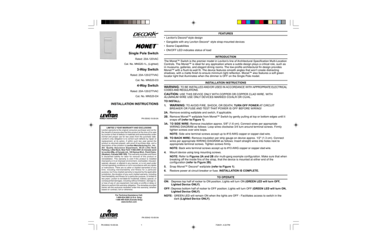
FEATURES COLLECTION BY LEVITON • Leviton's Decora® style design • Gangable with any Leviton Decora® style strap-mounted devices • Scene Capabilities • ON/OFF LED indicates status of load Single Pole Switch Rated: 20A-120VAC Cat. No. MNS20-1L, (Lighted) 3-Way Switch Rated: 20A-120/277VAC INTRODUCTION The Monet™ Switch is the premier model in Leviton’s line of Architectural Specification Multi-Location Controls. The Monet™ is ideal for any application where a subtle design plays a critical role, such as in museums, galleries, and elegant dining rooms. The low-profile architectural fin design provides Monet™ with a flush-to-wall fit. The device features smooth angles that won’t create distracting shadows, with a matte finish to ensure minimum light reflection. Monet™ also features a soft green locator light that illuminates when the dimmer is OFF on the Single Pole model. Cat. No. MNS20-D3 INSTALLATION INSTRUCTIONS 4-Way Switch Rated: 20A-120/277VAC Cat. No. MNS20-D4 INSTALLATION INSTRUCTIONS WARNING: TO BE INSTALLED AND/OR USED IN ACCORDANCE WITH APPROPRIATE ELECTRICAL CODES AND REGULATIONS. CAUTION: USE THIS DEVICE ONLY WITH COPPER OR COPPER CLAD WIRE. WITH ALUMINUM WIRE USE ONLY DEVICES MARKED CO/ALR OR CU/AL. TO INSTALL: 1. WARNING: TO AVOID FIRE, SHOCK, OR DEATH; TURN OFF POWER AT CIRCUIT BREAKER OR FUSE AND TEST THAT POWER IS OFF BEFORE WIRING! 2A. Remove existing wallplate and switch, if applicable. PK-93042-10-00-0A LIMITED 2 YEAR WARRANTY AND EXCLUSIONS Leviton warrants to the original consumer purchaser and not for the benefit of anyone else that this product at the time of its sale by Leviton is free of defects in materials and workmanship under normal and proper use for two years from the purchase date. Leviton’s only obligation is to correct such defects by repair or replacement, at its option, if within such two year period the product is returned prepaid, with proof of purchase date, and a description of the problem to Leviton Manufacturing Co., Inc., Att: Quality Assurance Department, 59-25 Little Neck Parkway, Little Neck, New York 11362-2591 (In Canada send to Leviton Mfg. of Canada Ltd., 165 Hymus Blvd., Point Claire, (Quebec), Canada H9R 1E9). This warranty excludes and there is disclaimed liability for labor for removal of this product or reinstallation. This warranty is void if this product is installed improperly or in an improper environment, overloaded, misused, opened, abused, or altered in any manner, or is not used under normal operating conditions or not in accordance with any labels or instructions. There are no other or implied warranties of any kind, including merchantability and fitness for a particular purpose, but if any implied warranty is required by the applicable jurisdiction, the duration of any such implied warranty, including merchantability and fitness for a particular purpose, is limited to two years. Leviton is not liable for incidental, indirect, special, or consequential damages, including without limitation, damage to, or loss of use of, any equipment, lost sales or profits or delay or failure to perform this warranty obligation. The remedies provided herein are the exclusive remedies under this warranty, whether based on contract, tort or otherwise. For Technical Assistance Call: 1-800-824-3005 (U.S.A. Only) 1 800 405-5320 (Canada Only) www.leviton.com 2B. Remove Monet™ wallplate from Monet™ Switch by gently pulling at top or bottom edges until it snaps off (refer to Figure 1). 3A. TO SIDE WIRE: Remove insulation approx. 5/8" (1.6 cm). Connect wires per appropriate WIRING DIAGRAM as follows: Loop wires clockwise 3/4 turn around terminal screws. Firmly tighten screws over wire loops. NOTE: Side wire terminal screws accept up to #10 AWG copper or copper clad wire. 3B. TO BACK WIRE: Remove insulation per strip gauge on device approx. 1/2" (1.3 cm). Connect wires per appropriate WIRING DIAGRAM as follows: Insert straight wires into holes next to appropriate terminal screws. Tighten screws firmly. NOTE: Back wire terminal screws accept up to #10 AWG copper or copper clad wire. 4. Mount device using long mounting screws. NOTE: Refer to Figures 2A and 2B sfor multi-gang example configuration. Make sure that when breaking off the inside fins of the strap, that the device is mounted at either end of the configuration (refer to Figure 2B). 5. Snap Monet™ Decora® wallplate (refer to Figure 1). 6. Restore power at circuit breaker or fuse. INSTALLATION IS COMPLETE. TO OPERATE ON: Depress top half of rocker to ON position; Lights will turn ON (GREEN LED will turn OFF, Lighted Device ONLY). OFF: Depress bottom half of rocker to OFF position; Lights will turn OFF (GREEN LED will turn ON, Lighted Device ONLY). NOTE: GREEN LED will remain ON when the lights are OFF - Facilitates access to switch in the dark (Lighted Device ONLY). PK-93042-10-00-0A PK-93042-10-00-0A 1 7/26/01, 4:22 PM Figure 1 - Wallplate Installation/Removal Wiring Diagram 1 - Single Location Control Application Switch MNS20-1L Hot (Black) Black Line 120VAC, 60Hz Green Ground Load White Neutral (White) Wiring Diagram 2 - Two Location Control Application 2 Travelers: Brass Screw to Brass Screw 1 To Common Terminal (Black Screw) Switch MNS20-D3 Figure 2A - Multi-gang Configuration No Fins Broken Off (5 Gang Outlet Box) Hot (Black) Switch MNS20-D3 1 1 Black Load Line 120/277VAC, 60Hz Green Ground Green Ground 2 White 2 Neutral (White) Wiring Diagram 3 - Three Location Control Application Figure 2B - Multi-gang Configuration Fins Broken Off (3 Gang Outlet Box) 1 To Common Terminal (Black Screw) 2 Travelers: Brass Screw to Brass Screw Switch MNS20-D4 Switch MNS20-D3 Switch MNS20-D3 OUT Hot (Black) 1 2 1 IN Black 2 IN OUT Load Line 120/277VAC, 60Hz Green Ground Green Ground 2 2 Neutral (White) PK-93042-10-00-0A PK-93042-10-00-0A 2 7/26/01, 4:22 PM Green Ground White FOLD SCHEME 8.5¨ Front Panel Cat. No. 8.5¨ Front Panel Cat. No. Front Panel Cat. No. Fold Line Center Line PK-93042-10-00-0A 3 7/26/01, 4:22 PM
