Phywe No. 06778.00
advertisement

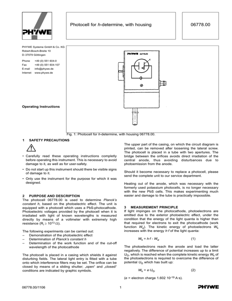
Photocell for h-determine, with housing 06778.00 PHYWE Systeme GmbH & Co. KG Robert-Bosch-Breite 10 D-37079 Göttingen Phone +49 (0) 551 604-0 Fax +49 (0) 551 604-107 E-mail info@phywe.de Internet www.phywe.de Operating Instructions Fig. 1: Photocell for h-determine, with housing 06778.00. 1 SAFETY PRECAUTIONS The upper part of the casing, on which the circuit diagram is printed, can be removed after loosening the lateral screw. The photocell is placed in a tube with two apertures. The bridge between the orifices avoids direct irradiation of the central anode, thus avoiding disturbances due to photoemission from the anode. • Carefully read these operating instructions completly before operating this instrument. This is necessary to avoid damage to it, as well as for user-safety. • Do not start up this instrument should there be visible signs of damage to it. Should it become necessary to replace a photocell, please send the complete unit to our service department. • Only use the instrument for the purpose for which it was designed. Heating out of the anode, which was necessary with the formerly used potassium photocells, is no longer necessary with the new PbS cells. This makes experimenting much easier and damage to the tube is practically impossible. 2 PURPOSE AND DESCRIPTION The photocell 06778.00 is used to determine Planck’s constant h, based on the photoelectric effect. The unit is equipped with a photocell which uses a PbS-photocathode. Photoelectric voltages provided by the photocell when it is irradiated with light of known wavelengths is measured directly by means of a voltmeter with extremely high resistance (Ri ≥ 1013 Ω). 3 MEASUREMENT PRINCIPLE If light impinges on the photocathode, photoelectrons are emitted due to the exterior photoelectric effect, under the condition that the energy of the light quanta is higher than that required for electrons to exit the photocathode (work function Wa). The kinetic energy of photoelectrons Wk increases with the energy h·f of the light quanta: The following experiments can be carried out: – Demonstration of the photoelectric effect – Determination of Planck’s constant h – Determination of the work function and of the cut-off wavelength of the photocathode Wk = h·f - Wa. The photoelectrons reach the anode and load the latter negatively. The difference of potential increases up to a limit UG, which is reached when the complete kinetic energy Wk of the photoelectrons is required to overcome the difference of potential UG which has built up: The photocell is placed in a casing which shields it against disturbing fields. The lateral light entry is fitted with a tube onto which interference filters may be set. The orifice can be closed by means of a sliding shutter; „open“ and „closed“ conditions are indicated by graphic symbols. Wk = e·UG. (e = electron charge 1.602 10-19 A·s). 06778.00/1106 (1) 1 (2) Fig. 2: Measurement set-up to determine h with photocell 06778.00. From equations (1) and (2) one obtains: e·UG = h·f - Wa. will occur. The precedent measurement amplifier model with the order No. 11761.93, which is present in many didactic equipment kits, is also adequate. The operating modus „electrometer“ and the amplification factor 1 must be set on the measurement amplifier. Practically any available analogue or digital multimeter can be connected to the output of the measurement amplifier. (3) If UG is measured at least for two wavelengths, the two unknown factors h and Wa can be determined from equation (3). Normally, however, more than two measurements are made and UG is plotted as a function of f. After (3) is modified to UG = h⋅ f e − Wa e Carrying out a measurement: – The amplifier input is shorted by pressing button „0“ when the light entry of the photocell is closed. Whilst the button „0“ is depressed, the read-out on the measurement amplifier is set to zero by means of the „0“ setting knob. – Open the sliding shutter and record the indicated voltage UG. – Close the sliding shutter, exchange the filter and repeat until the measurements have been carried out with all filters. (4) t becomes apparent that this is a straight line with slope h/e. The work function may be assessed from the negative ordinate section. However, for PbS cathods, this value does not have the significance of a physical constant, as it is significantly influenced by the manufacturing technology of the photocathode. Once h has been determined, Wa can be calculated from the intersection of the compensating straight line with the abscissa, the so-called limit frequency fmin (the long wave limit wavelength λmax = c/fmin is more usual), for which UG = 0. In this case, Wa = h·fmin. The measurement values are then plotted as shown in fig. 3 as an example. Planck’s constant h is determined from the slope of the straight line, using equation (4). For the measurement example shown in fig. 3, one obtains the value h = 6.05·10-34 Ws. Comparing this value with the value given in literature, h = 6.625·10-34 Ws, the error is found to be -8.7%. From the intersection of the straight line with x axis at fmin = 3.3·1014 Hz, one finds a limit wavelength of λmax = 908 nm for the present example. 4 HANDLING The experimental set-up is shown in fig. 2 and is carried out using the parts mentioned in the list of accessories (cf. section 5). Instead of the illustrated set-up, the unit can also be set up on an optical bench by means of the provided threaded rod which can be screwed into the base plate. 4.1 Indications concerning measurement precision The determination of Planck’s constant using the photoelectric effect is not as precise as with other procedures (e.g. the short wave limit of the X-ray retardation spectrum). The errors are partly due to unavoidable photoemission from the anode as well as to disturbing effects in the photocells. With our photocells, systematic deviations of h from literature values are within ± 20%. The scattering degree of repeated measurements with the same cell is low. Due to historical reasons, this method to determine h should be the one used preferentially during classes. The spectral lamp which is connected to the ballast coil should be switched on about 15 minutes before the first measurement is carried out. To carry out measurements, it is shifted near the light entrance orifice (distance approximately 2 cm), an interference filter being pushed over the tube. The BNC socket is connected by a shielded cable to the input of the measurement amplifier. It is absolutely necessary to use either this measurement amplifier, or another one with an input resistance Ri ≥ 1013 Ω; otherwise, measurement errors 06778.00/1106 2 2 1,5 UG ___ V 1 0,5 0 0 1 2 3 4 5 6 . 7 -14 8 f/10f-3410 Hz Hz 9 Fig. 3: Measurement example. 5 LIST OF ACCESSORIES (cf. Fig. 2) Photocell to determine h Mounting plate, 210 mm x 160 mm Experimental lamp 6 Spectral lamp Hg100, pico 9 Ballast coil for spectral lamps Measurement amplifier, universal Voltmeter 0.3...300 VDC, 10...300 VAC Interference filters, set of 3 Interference filters, set of 2 Shielded BNC cable, l = 750 mm Connecting cable 25 cm, red Connecting cable 25 cm, blue 7 WASTE DISPOSAL The packaging consists predominately of environmental compatible materials that can be passed on for disposal by the local recycling service. 06778.00 13002.00 11615.05 08120.14 13662.93 13626.93 07035.00 08461.00 08463.00 07542.11 07360.01 07360.04 Should you no longer require this product, do not dispose of it with the household refuse. Please return it to the address below for proper waste disposal. PHYWE Systeme GmbH & Co. KG Abteilung Kundendienst Robert-Bosch-Breite 10 D-37079 Göttingen Phone +49 (0) 551 604-274 Fax +49 (0) 551 604-246 6 GUARANTEE We guarantee the instrument supplied by us for a period of 24 months within the EU, or for 12 months outside of the EU. This guarantee does not cover natural wear nor damage resulting from improper handling. The manufacturer can only be held responsible for the function and technical safety characteristics of the instrument, when maintenance, repairs and changes to the instrument are only carried out by the manufacturer or by personnel who have been explicitly authorized by him to do so. 06778.00/1106 3

