LEP 2.2.05 -00 Michelson interferometer
advertisement
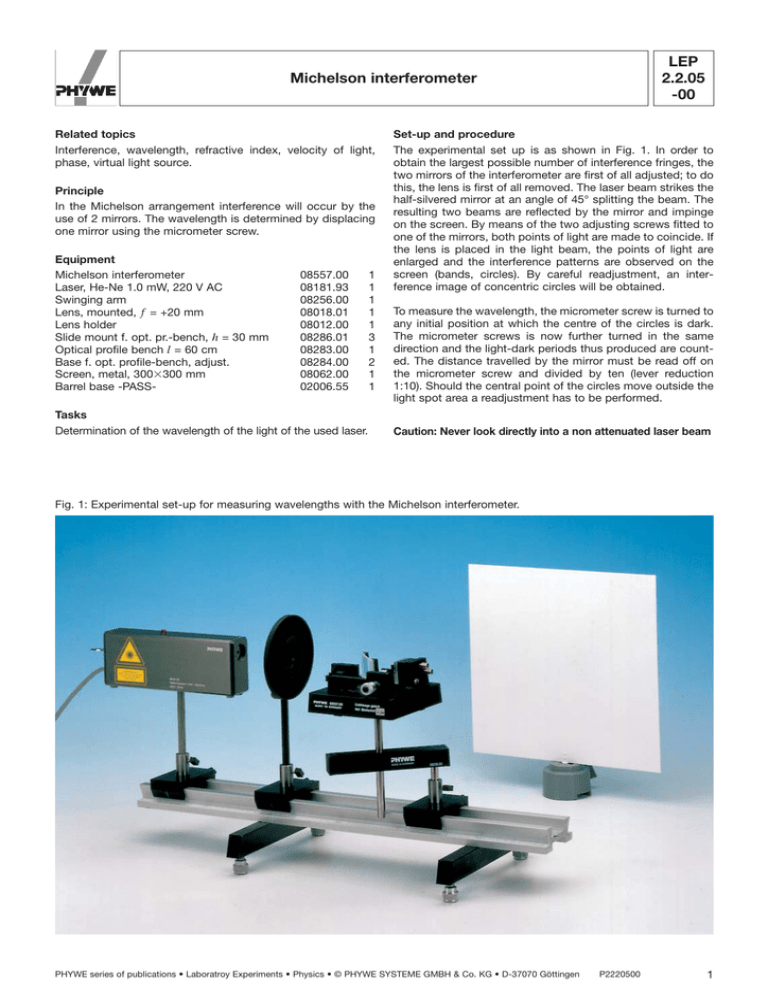
LEP 2.2.05 -00 Michelson interferometer Related topics Interference, wavelength, refractive index, velocity of light, phase, virtual light source. Principle In the Michelson arrangement interference will occur by the use of 2 mirrors. The wavelength is determined by displacing one mirror using the micrometer screw. Equipment Michelson interferometer Laser, He-Ne 1.0 mW, 220 V AC Swinging arm Lens, mounted, f = +20 mm Lens holder Slide mount f. opt. pr.-bench, h = 30 mm Optical profile bench l = 60 cm Base f. opt. profile-bench, adjust. Screen, metal, 300300 mm Barrel base -PASS- 08557.00 08181.93 08256.00 08018.01 08012.00 08286.01 08283.00 08284.00 08062.00 02006.55 Tasks Determination of the wavelength of the light of the used laser. 1 1 1 1 1 3 1 2 1 1 Set-up and procedure The experimental set up is as shown in Fig. 1. In order to obtain the largest possible number of interference fringes, the two mirrors of the interferometer are first of all adjusted; to do this, the lens is first of all removed. The laser beam strikes the half-silvered mirror at an angle of 45° splitting the beam. The resulting two beams are reflected by the mirror and impinge on the screen. By means of the two adjusting screws fitted to one of the mirrors, both points of light are made to coincide. If the lens is placed in the light beam, the points of light are enlarged and the interference patterns are observed on the screen (bands, circles). By careful readjustment, an interference image of concentric circles will be obtained. To measure the wavelength, the micrometer screw is turned to any initial position at which the centre of the circles is dark. The micrometer screws is now further turned in the same direction and the light-dark periods thus produced are counted. The distance travelled by the mirror must be read off on the micrometer screw and divided by ten (lever reduction 1:10). Should the central point of the circles move outside the light spot area a readjustment has to be performed. Caution: Never look directly into a non attenuated laser beam Fig. 1: Experimental set-up for measuring wavelengths with the Michelson interferometer. PHYWE series of publications • Laboratroy Experiments • Physics • © PHYWE SYSTEME GMBH & Co. KG • D-37070 Göttingen P2220500 1 LEP 2.2.05 -00 Michelson interferometer Fig. 2: Michelson interferometer set up. Fig. 3: Formation of circles on interference. Theory and evaluation If 2 waves of the same frequency v but of different amplitude and different phase impinge on one point they are superimposed, or interfere, so that: Based on the different light paths, the phase difference, using the symbols of Fig. 3, is: d 2p 2d cos u l (2) where l is the wavelength of the light used in the experiment. y = a1 sin (vt – a1) + a2 sin (vt – a2) . The intensity distribution for a1 = a2 = a according to (1) is: The resulting wave can be described as I A2 4a2 cos2 y = A sin (t – a) A2 = a21 + a22 + 2a1a2 cos (1) and the phase difference 2d cos = m; m = 1, 2, … (4) i.e. circles are produced for a fixed value of m and d since remains constant (see Fig. 3). = a1 – a2 . In a Michelson interferometer, light is split up into two beams by a half-silvered glass plate (amplitude splitting), reflected by two mirrors, and passed again through the glass plate to produce interference phenomena behind it. A lens is inserted between the light beam and the glass plate so that the light source lies at the focal point, since only enlarged light spots can exhibit interference rings. If the actual mirror M1 is replaced by its virtual image M’1 = M2 which is formed by reflection at the glass plate, a point P of the real light source is formed as the points P’ and P’’ of the virtual light sources L1 and L2. P2220500 (3) Maxima thus occur if is a multiple of 2p, i.e. from equation (2), if with the amplitude 2 d 2 If the position of the movable mirror M1 is changed so that d for example decreases then, according to equation (4), the diameter of the ring will also decrease since m is fixed for this ring. A ring thus dissapears each time d is reduced by l/2. The ring pattern disappears if d = 0. If M1 and M2 are not parallel, curved bands are obtained which are converted to straight bands when d = 0. To measure the wavelength of the light, 500 ring changes were counted. A 158 mm displacement of the mirrow was measured. From this, the wavelength was obtained as: l = 632 nm. PHYWE series of publications • Laboratory Experiments • Physics • © PHYWE SYSTEME GMBH & Co. KG • D-37070 Göttingen
