9259/Jaro Resistor/SR series
advertisement

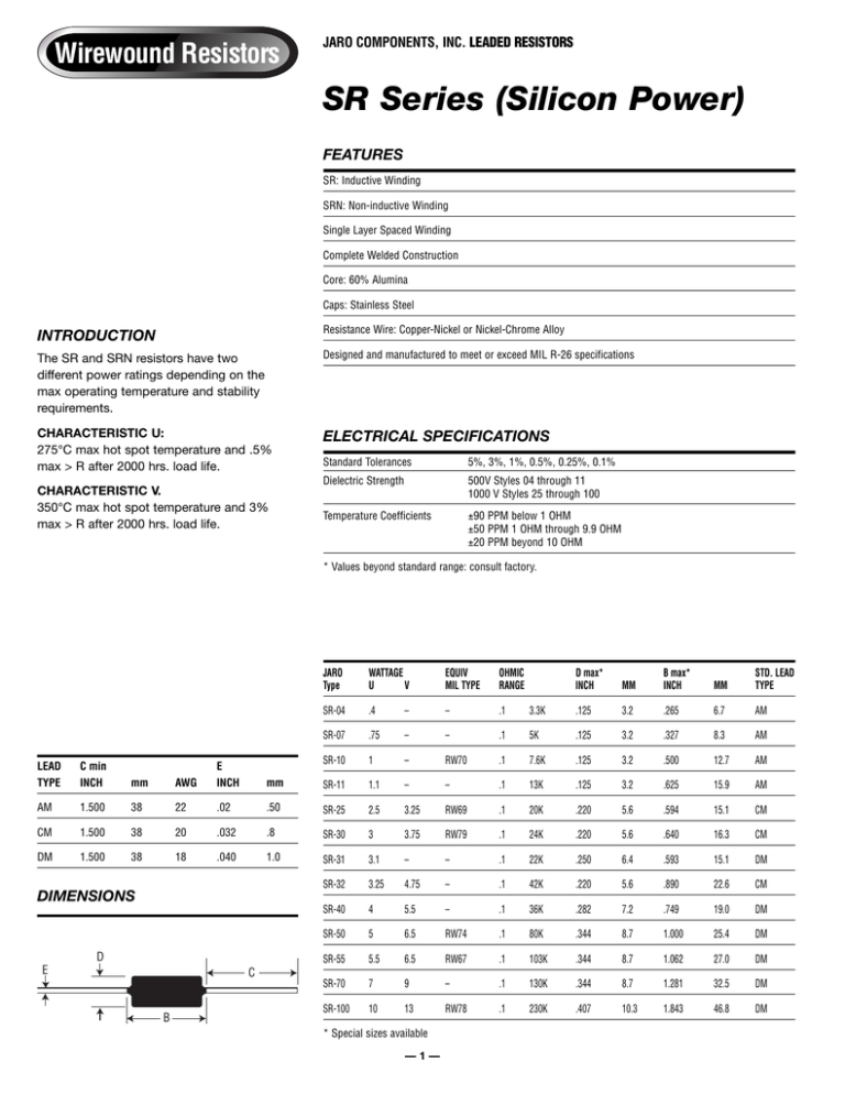
Wirewound Resistors JARO COMPONENTS, INC. LEADED RESISTORS SR Series (Silicon Power) FEATURES SR: Inductive Winding SRN: Non-inductive Winding Single Layer Spaced Winding Complete Welded Construction Core: 60% Alumina Caps: Stainless Steel INTRODUCTION Resistance Wire: Copper-Nickel or Nickel-Chrome Alloy The SR and SRN resistors have two different power ratings depending on the max operating temperature and stability requirements. Designed and manufactured to meet or exceed MIL R-26 specifications CHARACTERISTIC U: 275°C max hot spot temperature and .5% max > R after 2000 hrs. load life. ELECTRICAL SPECIFICATIONS CHARACTERISTIC V. 350°C max hot spot temperature and 3% max > R after 2000 hrs. load life. Standard Tolerances 5%, 3%, 1%, 0.5%, 0.25%, 0.1% Dielectric Strength 500V Styles 04 through 11 1000 V Styles 25 through 100 Temperature Coefficients ±90 PPM below 1 OHM ±50 PPM 1 OHM through 9.9 OHM ±20 PPM beyond 10 OHM * Values beyond standard range: consult factory. HOW TO ORDER: TYPE VALUE TOLERANCE SR-30 1K 1% 3 Watt (Inductive) For non-inductive winding change SR to SRN LEAD TYPE C min INCH mm AM 1.500 CM DM JARO Type WATTAGE U V EQUIV MIL TYPE OHMIC RANGE D max* INCH MM B max* INCH MM STD. LEAD TYPE SR-04 .4 – – .1 3.3K .125 3.2 .265 6.7 AM SR-07 .75 – – .1 5K .125 3.2 .327 8.3 AM SR-10 1 – RW70 .1 7.6K .125 3.2 .500 12.7 AM AWG E INCH mm SR-11 1.1 – – .1 13K .125 3.2 .625 15.9 AM 38 22 .02 .50 SR-25 2.5 3.25 RW69 .1 20K .220 5.6 .594 15.1 CM 1.500 38 20 .032 .8 SR-30 3 3.75 RW79 .1 24K .220 5.6 .640 16.3 CM 1.500 38 18 .040 1.0 SR-31 3.1 – – .1 22K .250 6.4 .593 15.1 DM SR-32 3.25 4.75 – .1 42K .220 5.6 .890 22.6 CM SR-40 4 5.5 – .1 36K .282 7.2 .749 19.0 DM SR-50 5 6.5 RW74 .1 80K .344 8.7 1.000 25.4 DM SR-55 5.5 6.5 RW67 .1 103K .344 8.7 1.062 27.0 DM SR-70 7 9 – .1 130K .344 8.7 1.281 32.5 DM SR-100 10 13 RW78 .1 230K .407 10.3 1.843 46.8 DM DIMENSIONS D E C B * Special sizes available —1— Wirewound Resistors 6600 Park of Commerce Blvd. Boca Raton, FL 33487 561-241-6700 Phone 561-241-3328 Fax http://www.jaro1.com JARO COMPONENTS, INC. LEADED RESISTORS SR Series MATERIALS SPECIFICATIONS CORE: 60% Alumina CAPS: Stainless Steel LEADS: Tinned Copperclad RESISTANCE WIRE: 300 ohm/Circ. Mil. ft. for low values 600 ohm/Circ. Mil ft. for high values COATING: High temperature silicon compound INK: Epoxy ELECTRICAL SPECIFICATIONS STANDARD MARKING INCLUDES: Tolerance Wattage (Special marking available on request.) 5%, 3%, 1%, 0.5%, 0.25%, 0.1% Dielectric Strength: 500 Volts AC styles SR-04-07-10-11 Insulation: 1000M ohm minimum 1000 Volts AC from styles SR-25 to SR-100 Low Thermal E.M.F. JARO 5W 1K Very Low Thermal Noice 1% Designed and manufactured to meet or exceed MIL R-26 specifications DERATING VS. AMBIENT TEMPERATURE 100 PERCENT OF RATED POWER Value Standard Tolerances: 80 60 V 40 U 20 0 25 100 150 200 250 300 AMBIENT TEMPERATURE °C —2— 350 Ambient Temperature (ºC)


