AN-1166
APPLICATION NOTE
One Technology Way • P.O. Box 9106 • Norwood, MA 02062-9106, U.S.A. • Tel: 781.329.4700 • Fax: 781.461.3113 • www.analog.com
HDMI Sink Jitter Tolerance Issues for Devices that Use
an HDMI Mux and HDMI Receiver
by Peter Checkovich
INTRODUCTION
A standard means to increase the overall number of HDMI
inputs to a system is to use an HDMI mux with several inputs
whose output feeds one of the inputs of an HDMI receiver. This
results in two cascaded stages to handle the TMDS signals
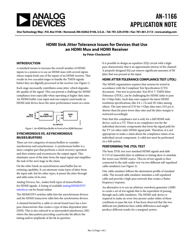
before they are digitally processed in the receiver (see Figure 1)
Each stage necessarily contributes some jitter, which degrades
the quality of the signal. This can present a challenge for HDMI
compliance tests especially when operating at higher data rates.
An HDMI buffer (one input and one output) used inside an
HDMI sink device faces the same performance issues as a mux.
HDMI
MUX/BUFFER
HDMI
Rx
Rx INPUTS
10965-001
MUX
INPUTS
Figure 1. An HDMI Mux/Buffer in Front of an HDMI Receiver
SYNCHRONOUS VS. ASYNCHRONOUS
MUXES/BUFFERS
There are two categories of muxes/buffers to consider:
synchronous and asynchronous. A synchronous buffer is a
more complex part that performs a clock recovery operation
and then retimes and reconstructs the output signal. This
eliminates most of the jitter from the input signal and simplifies
the task of the next stage in the chain.
On the other hand, an asynchronous mux/buffer has no
retiming capability. It can attenuate some types of jitter from
the input side, but for other types, it passes the jitter through
and adds some of its own.
It is possible to design an equalizer (EQ) circuit with a highpass characteristic that is an approximate inverse of the channel.
A properly designed EQ can remove significant amounts of ISI
jitter that was present at the input.
HDMI JITTER TOLERANCE COMPLIANCE TEST (JTOL)
The HDMI organization requires that systems be tested in
accordance with the Compliant Test Specification (CTS)
document. One test in particular, Test ID 8-7: TMDS Jitter
Tolerance (JTOL), can be challenging for HDMI sinks to pass
for 3 Gbps links. Such data rates support the latest HDMI
resolution specifications, like 4 k × 2 k and 3D video among
others. The unit interval (UI) for 3 Gbps data rates (333 ps) is
shorter than for prior lower data rates and the jitter margin is
restricted accordingly.
Note that this compliance test is only for a full HDMI sink
device, such as a TV. There is no compliance test for the
individual electronic components that form the signal path for
the TV (or other sink) HDMI signal path. Therefore, it is not
appropriate to make a claim about the compliance status of an
individual circuit component. A valid test must be performed
on a full system.
PERFORMING THE JTOL TEST
The basic JTOL test uses standard HDMI signals and adds
0.3 UI of sinusoidal jitter in addition to timing skew to simulate
the worst-case HDMI source. This set of test signals is then
connected to the sink-under-test via two different self-equalized
cable emulators (see Figure 2).
One cable emulator follows the attenuation profile of standard
cable. The second cable emulator simulates a self-equalized
cable and provide a high-pass network that creates a flatter
frequency response.
Analog Devices, Inc., makes both types of muxes/buffers
for HDMI signals. A listing of available analog/HDMI/DVI
interfaces can be found online.
The HDMI/DVI switches table lists the asynchronous devices
and the HDMI transceiver table lists the synchronous devices.
A channel formed by a cable or circuit board trace has a lowpass characteristic that creates a type of data-dependent jitter
(DDJ). This is also referred to as intersymbol interference (ISI)
where the data pattern preceding a particular bit affects the
timing and/or amplitude of the bit in question.
An alternative is to use an arbitrary waveform generator (ARB)
to create a set of test signals that is the equivalent of passing
through such cable emulators. The HDMI sink device is
required to make an error-free picture under either of these
conditions to pass the test. It has been observed that the two
different test platforms have subtle differences and might
produce different results for a marginal system.
Rev. 0 | Page 1 of 2
AN-1166
Application Note
SINK DUT
TP2
TP1
TMDS
GENERATOR
TP3
INTERCONNECT
PC BOARD
OR CABLE
HDMI
MUX/BUFFER
CABLE
EMULATOR
TP4
10965-002
JITTER
DRIVE
HDMI
Rx
Figure 2. Block Diagram for HDMI Compliance JTOL Test ing (Test ID 8-7)
A problem can arise when testing with a self-equalized cable
emulator between TP1 and TP2 and using an asynchronous
buffer/mux between TP2 and TP3. Three cascaded stages
provide an EQ function and create an over-equalized condition
that has too much jitter for the HDMI receiver to reliably
process and the test can fail.
10965-003
On the other hand, an asynchronous mux/buffer in the center
stage can remove most of the jitter it receives at TP2. A
reconstructed data signal is presented to the HDMI Rx device,
which has low jitter that is within the jitter budget limits of the
receiver. This enables the system to pass the JTOL test.
CONCLUSION
Figure 3. Eye Diagram for 3 Gbps Signal
with 0.3 UI Sinusoidal Jitter at TP1
SIGNAL CHAIN CONSIDERATIONS
A channel formed by a cable or circuit board trace has a lowpass characteristic that creates a type of data-dependent jitter
(DDJ). This is also referred to as intersymbol interference (ISI)
where the data pattern preceding a particular bit affects the
timing and/or amplitude of the bit in question.
It is possible to design an equalizer (EQ) circuit with a highpass characteristic that is an approximate inverse of the channel.
A properly designed EQ can remove significant amounts of ISI
jitter that was present at the input.
The HDMI buffer/mux usually has a cable at its input and
provides input EQ at TP2 to enable the use of longer cables.
Similarly, the HDMI receiver might also have inputs connected
directly to a cable, and it also provides input EQ at TP4.
Using an asynchronous HDMI mux/buffer in front of an HDMI
receiver can present challenges in passing the 3 Gbps HDMI
JTOL test in the CTS when using a self-equalized cable
emulator. This is caused by an over-equalization condition
which adds excessive jitter. A synchronous mux/buffer can
perform better because by retiming the signal, it removes most
of all types of jitter from its input and presents a clean signal to
the HDMI receiver.
The CTS JTOL test presents a significant challenge at 3 Gbps.
Therefore, it is highly recommended to conduct an early
investigation of this aspect of system performance to see if the
component selection and system design perform well enough
to pass this test.
REVISION HISTORY
12/12—Revision 0: Initial Version
©2012 Analog Devices, Inc. All rights reserved. Trademarks and
registered trademarks are the property of their respective owners.
AN10965-0-12/12(0)
Rev. 0 | Page 2 of 2


