3 Phase Controlled Rectifier - Creative Power Technologies
advertisement
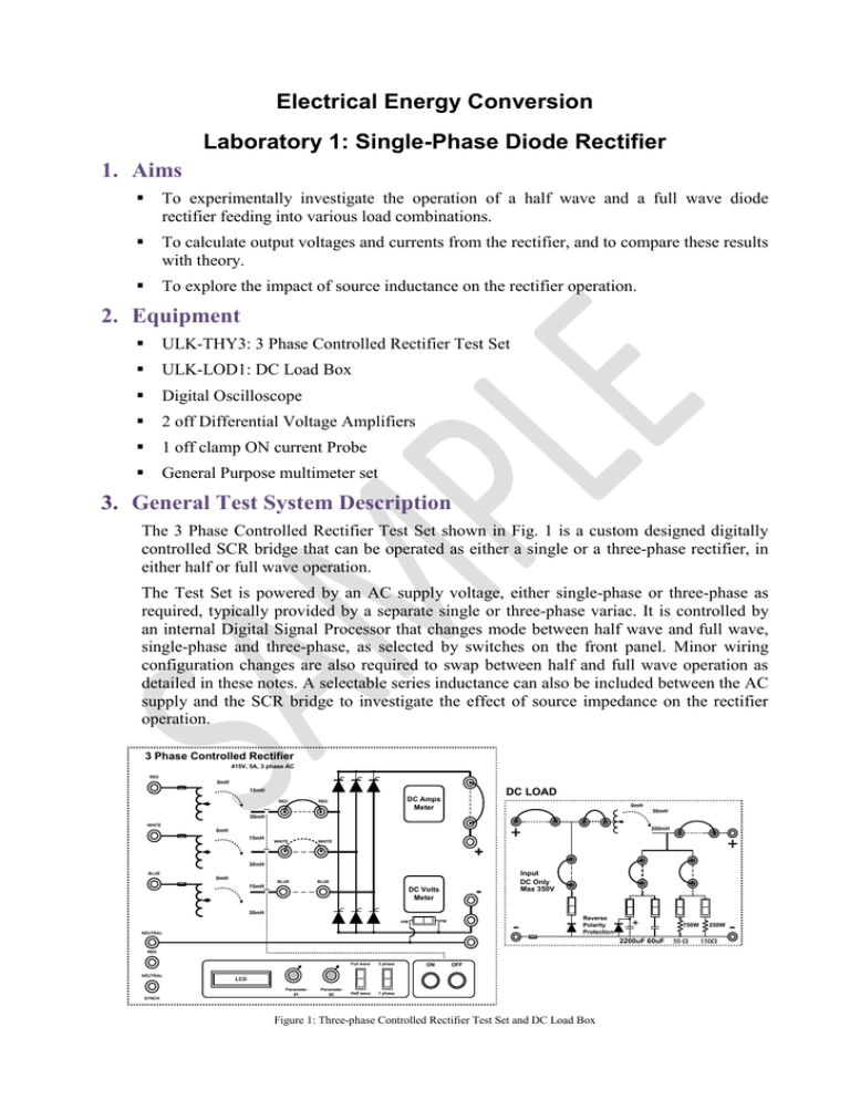
Electrical Energy Conversion Laboratory 1: Single-Phase Diode Rectifier 1. Aims To experimentally investigate the operation of a half wave and a full wave diode rectifier feeding into various load combinations. To calculate output voltages and currents from the rectifier, and to compare these results with theory. To explore the impact of source inductance on the rectifier operation. 2. Equipment ULK-THY3: 3 Phase Controlled Rectifier Test Set ULK-LOD1: DC Load Box Digital Oscilloscope 2 off Differential Voltage Amplifiers 1 off clamp ON current Probe General Purpose multimeter set 3. General Test System Description The 3 Phase Controlled Rectifier Test Set shown in Fig. 1 is a custom designed digitally controlled SCR bridge that can be operated as either a single or a three-phase rectifier, in either half or full wave operation. The Test Set is powered by an AC supply voltage, either single-phase or three-phase as required, typically provided by a separate single or three-phase variac. It is controlled by an internal Digital Signal Processor that changes mode between half wave and full wave, single-phase and three-phase, as selected by switches on the front panel. Minor wiring configuration changes are also required to swap between half and full wave operation as detailed in these notes. A selectable series inductance can also be included between the AC supply and the SCR bridge to investigate the effect of source impedance on the rectifier operation. 3 Phase Controlled Rectifier 415V, 5A, 3 phase AC RED 0mH DC LOAD 15mH RED DC Amps Meter RED 0mH 50mH 30mH WHITE + 0mH 15mH WHITE WHITE 200mH + + 30mH Input DC Only Max 350V BLUE 0mH BLUE BLUE 15mH - DC Volts Meter 30mH - FW HW NEUTRAL Reverse Polarity Protection + 2200uF 60uF RED NEUTRAL Full wave 3 phase Half wave 1 phase ON OFF LCD Parameter #1 Parameter #2 SYNCH Figure 1: Three-phase Controlled Rectifier Test Set and DC Load Box 750W 50 250W 150 -

