Resistance and Ohm`s Law Notes
advertisement

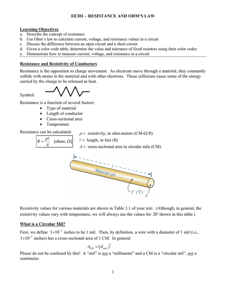
EE301 – RESISTANCE AND OHM’S LAW Learning Objectives a. Describe the concept of resistance b. Use Ohm’s law to calculate current, voltage, and resistance values in a circuit c. Discuss the difference between an open circuit and a short circuit d. Given a color code table, determine the value and tolerance of fixed resistors using their color codes e. Demonstrate how to measure current, voltage, and resistance in a circuit Resistance and Resistivity of Conductors Resistance is the opposition to charge movement. As electrons move through a material, they constantly collide with atoms in the material and with other electrons. These collisions cause some of the energy carried by the charge to be released as heat. Symbol: Resistance is a function of several factors: Type of material Length of conductor Cross-sectional area Temperature Resistance can be calculated: R [ohms, ] A resisitvity, in ohm-meters (CM- /ft) length, in feet (ft) A cross-sectional area in circular mils (CM) Resistivity values for various materials are shown in Table 3.1 of your text. (Although, in general, the resistivity values vary with temperature, we will always use the values for 20 shown in this table.) What is a Circular Mil? First, we define 1103 inches to be 1 mil. Then, by definition, a wire with a diameter of 1 mil (i.e., 1103 inches) has a cross-sectional area of 1 CM. In general: ACM d mils Please do not be confused by this! A “mil” is not a “millimeter” and a CM is a “circular mil”, not a centimeter. 2 1 EE301 – RESISTANCE AND OHM’S LAW Example: You have 1000 feet of copper wire whose diameter is note that for copper, 10.37 CM . ft 1 th of an inch. What is the resistance? 50 Solution: Consider: What is the diameter in mils? Consider: What is the cross-sectional area A in CM? Types of Resistors Two main categories of resistors are fixed and variable. Fixed resistors have an essentially constant value of resistance. Variable resistors have an adjustable value of resistance. Variable resistors can be used to adjust voltage (in which case they are called potentiometers) or to adjust current (in which case they are called rheostats). Resistor Color Coding Resistors usually have 4, 5 or 6 color bands. 4 color bands: Band 1: First Digit Band 2: Second Digit Band 3: Multiplier (i.e., number of zeros after second digit) Band 4: Tolerance 2 5 color bands: Band 1: First Digit Band 2: Second Digit Band 3: Third Digit Band 4: Multiplier Band 5: Tolerance EE301 – RESISTANCE AND OHM’S LAW Note that if there is no fourth band, the tolerance is 20% . Example: Determine the resistance of the carbon film resistors having the color codes shown below. Brown-Black-Brown-Gold Green-Blue-Yellow-Green-Silver Solution: Example: You pick up a resistor and note with fascination that it has three color bands: white-brownorange. What is the range of resistance values that you can be sure that this resistor falls within? Solution: 3 EE301 – RESISTANCE AND OHM’S LAW Ohm’s Law Ohm’s law states that current in a resistive circuit is directly proportional to the applied voltage and inversely proportional to resistance. I E R [amps, A] where E is voltage in volts, R is resistance in ohms, I is current in amperes. Ohm’s law is also expressed in the following forms: E IR [volts, V] E R [ohms, ] I Two different symbols are commonly used to represent voltage: E for sources V for loads (e.g., the voltage drop across a resistor) Note the polarities: If we have a resistor with voltage polarity labeled (as shown above), the positive-valued current reference arrow will always enter the positive terminal of the resistor. Example: Determine the current in the circuit below. Solution: 4 EE301 – RESISTANCE AND OHM’S LAW Example: Determine the voltage in the circuit below. Solution: Measuring Voltage Voltage and current is measured using voltmeters and ammeters. A device that can be used as a voltmeter and an ammeter is termed a multimeter. We use a Digital Multimeter or DMM in this course. Measure voltage by placing the voltmeter leads ACROSS the component whose voltage you wish to measure. Polarity can be determined by probe placement. Measuring Current The current that you wish to measure must pass THROUGH the meter. Be careful that the meter’s maximum current rating is not exceeded! 5 EE301 – RESISTANCE AND OHM’S LAW Polarity for measurements For the voltage across a resistor, always place the plus sign at the ___________ of the current reference arrow. To ensure the correct voltage sign on the DMM, place the RED lead where you think the “+” sign should be. For correct current polarity, the current should enter the RED lead of the DMM. Measuring Resistance An ohmmeter is a device used to measure the resistance of a component. Component resistance: You must ISOLATE the component that you are measuring from the circuit! You must remove the power source prior to measuring resistance! 6 EE301 – RESISTANCE AND OHM’S LAW Open Circuits Current can only exist where there is a conductive path. Since current is zero, the circuit has an infinite resistance. This is called an open circuit. R E E ohms I 0 Short Circuits A very low (or near zero) resistance is placed across a circuit Since resistance is near zero, all current will bypass the rest of circuit and go through the short. With zero resistance, current draw will approach the limits of the power source ( infinite current), frequently causing damage to wiring or the power source. I E E amps R 0 7 EE301 – RESISTANCE AND OHM’S LAW Example: Determine the readings, magnitude and polarity for each measurement. Solution: 8


