LLO Outside Light Level Sensor Data Sheet
advertisement
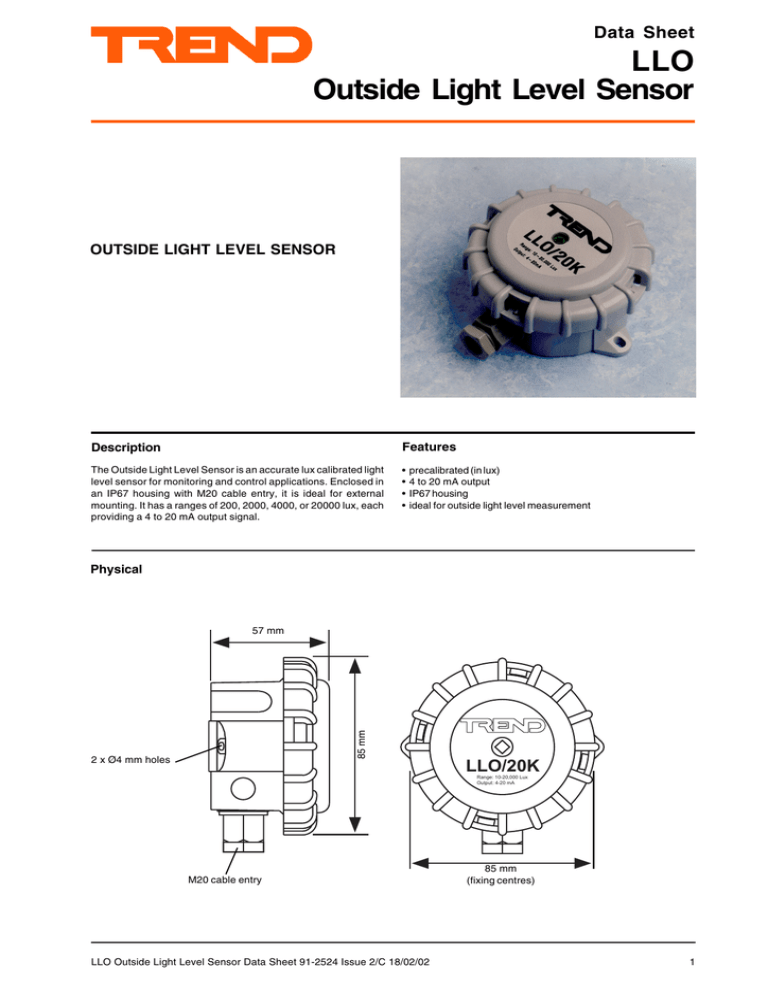
Data Sheet LLO Outside Light Level Sensor OUTSIDE LIGHT LEVEL SENSOR Description Features The Outside Light Level Sensor is an accurate lux calibrated light level sensor for monitoring and control applications. Enclosed in an IP67 housing with M20 cable entry, it is ideal for external mounting. It has a ranges of 200, 2000, 4000, or 20000 lux, each providing a 4 to 20 mA output signal. • • • • precalibrated (in lux) 4 to 20 mA output IP67 housing ideal for outside light level measurement Physical 85 mm 57 mm 2 x Ø4 mm holes L L O /2 0 K R a n g e : 1 0 -2 0 ,0 0 0 L u x O u tp u t: 4 -2 0 m A M20 cable entry LLO Outside Light Level Sensor Data Sheet 91-2524 Issue 2/C 18/02/02 85 mm (fixing centres) 1 LLO OUTSIDE LIGHT LEVEL SENSOR Data Sheet FUNCTIONALITY The sensor is hermetically sealed into the lid of an IP67 housing. The sensor is polarity independent, loop powered, giving a 4 to 20 mA signal proportional to light intensity (lux). OPERATIONAL DATA Typical Daylight Conditions illuminance (lux) 15 to 20 2000 20000+ Description dusk Recommended Service Illuminations illuminance (lux) Description 20 minimum ser vice illuminance in outside circulation areas reasonable daylight 30 outdoor stores, stockyards bright sunlight 50 exterior walkways, and car parks Note that hand held meters generally have a ±10% error. 75 docks and quays 150 circulation areas in industr y, stores, and stockrooms 200 minimum ser vice illuminance on task 500 general office and retail sales areas 1500 fine bench and machine work, and precision assembly CONNECTIONS INSTALLATION The sensor should be mounted on a north facing wall, out of direct sunlight. It should not be close to a light source such as street lighting. Sensor IQ 24 Vdc SIG Choose location Fix to the wall using two screws. Remove Lid. Route cable through cable gland. Connect to IQ controller via 2 part terminals Replace Lid Set up strategy Test PRODUCT CODE LLO/[range] SPECIFICATIONS Range 0K2 2K 4K 20K Output Accuracy Power supply Span adjustment range Zero adjustment range Field of view Ambient limits polarity independent terrminate screen at IQ end only Analogue input channel linked for current (I) Full installation details are given in the LLO Installation Instructions TG100153A. [range] Light Intensity 0K2 0 to 200 lux 2K 10 to 2000 lux 4K 10 to 4000 lux 20K 10 to 20000 lux IQ Scaling For IQ controllers the input channel must be set up correctly and the sensor type module must be set up with the correct scaling. For all IQ2 series controllers with firmware of version 2.1 or greater use the following table; for all other IQ controllers see the Sensor Scaling Reference Card TB100521A. Link input channel for current I, use sensor type scaling mode 5, characterise, with input type set to 2 (current) and the table below: :0 to 200 lux :10 to 2000 lux :10 to 4000 lux :10 to 20000 lux :4 to 20 mA :±5% across range Range Y E U L P I1 :10 to 33 Vdc :±10% 0K2 2 3 200 0 2 4 :±10% 2K 2 4 200 0 10 2 4 :124 ° maximum 4K 2 5 4000 10 2 4 :-25 to +70 °C 2 0 K 2 5 2 0 0 0 0 1 0 2 4 :0 to 95 %RH Connections :two part screw terminals for 0.5 to 2.5 mm2 System Accuracy (including controller) cross section area cable 0K2 :± 10 lux Dimensions :85 x 85 x 57 mm 2K :± 100.5 lux Weight : 154 gms 4K :± 201 lux Enclosure material :impact resistant ABS 20K :± 1005 lux Environment protection :IP67 Trend Control Systems Ltd reserves the right to revise this publication from time to time and make changes to without obligation to notify any person of such revisions or changes. I2 O1 20 0 O2 10 20 10 2000 20 10 4000 20 10 20000 the content hereof Trend Control Systems Ltd. P.O. Box 34 Horsham Sussex RH12 2YF England Tel:+44 (0)1403 211888 Fax:+44 (0)1403 241608 www.trend-controls.com 2 LLO Outside Light Level Sensor Data Sheet 91-2524 Issue 2/C 18/02/02
