Footstep Power Generation Using Piezo Electric Transducers

ISSN: 2277-3754
ISO 9001:2008 Certified
International Journal of Engineering and Innovative Technology (IJEIT)
Volume 3, Issue 10, April 2014
Footstep Power Generation Using Piezo Electric
Transducers
Kiran Boby, Aleena Paul K, Anumol.C.V, Josnie Ann Thomas, Nimisha K.K
Dept of EEE, MACE, Kothamangalam
Abstract— Man has needed and used energy at an increasing rate for the sustenance and well-being since time immemorial.
Due to this a lot of energy resources have been exhausted and wasted. Proposal for the utilization of waste energy of foot power with human locomotion is very much relevant and important for highly populated countries like India where the railway station, temples etc., are overcrowded all round the clock .When the flooring is engineered with piezo electric technology, the electrical energy produced by the pressure is captured by floor sensors and converted to an electrical charge by piezo transducers, then stored and used as a power source. And this power source has many applications as in agriculture, home application and street lighting and as energy source for sensors in remote locations.
Keywords — Piezoelectricity, PZT, PVDF, Inverter,
PIC16F873
II. RESEARCH ELABORATIONS
A.
STUDY OF PIEZO MATERIALS
Piezoelectric ceramics belong to the group of ferroelectric materials. Ferroelectric materials are crystals which are polar without an electric field being applied. The piezoelectric effect is common in piezo ceramics like PbTiO3, PbZrO3,
PVDF and PZT. The main component of the project is the piezoelectric material. The proper choice of the piezo material is of prime importance. For this, an analysis on the 2 most commonly available piezoelectric material - PZT and
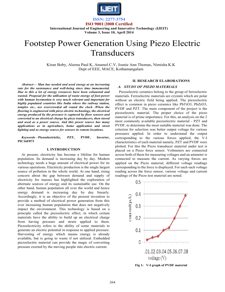
PVDF, to determine the most suitable material was done. The criterion for selection was better output voltage for various pressures applied. In order to understand the output corresponding to the various forces applied, the V-I characteristics of each material namely, PZT and PVDF were plotted. For this the Piezo transducer material under test is placed on a Piezo force sensor. Voltmeters are connected across both of them for measuring voltages and an ammeter is connected to measure the current. As varying forces are applied on the Piezo material, different voltage readings corresponding to the force is displayed. For each such voltage reading across the force sensor, various voltage and current readings of the Piezo test material are noted.
I. INTRODUCTION
At present, electricity has become a lifeline for human population. Its demand is increasing day by day. Modern technology needs a huge amount of electrical power for its various operations. Electricity production is the single largest source of pollution in the whole world. At one hand, rising concern about the gap between demand and supply of electricity for masses has highlighted the exploration of alternate sources of energy and its sustainable use. On the other hand, human population all over the world and hence energy demand is increasing day by day linearly.
Accordingly, it is an objective of the present invention to provide a method of electrical power generation from this ever increasing human population that does not negatively impact the environment. This technology is based on a principle called the piezoelectric effect, in which certain materials have the ability to build up an electrical charge from having pressure and strain applied to them.
Piezoelectricity refers to the ability of some materials to generate an electric potential in response to applied pressure.
Harvesting of energy which means energy is already available, but is going to waste if not utilized. Embedded piezoelectric material can provide the magic of converting pressure exerted by the moving people into electric current.
Fig 1: V-I graph of PVDF material
264
ISSN: 2277-3754
ISO 9001:2008 Certified
International Journal of Engineering and Innovative Technology (IJEIT)
Volume 3, Issue 10, April 2014
Fig 2: V-I graph of PZT
The voltage from PZT is around 2 V where as that of
PVDF is around 0.4V.We can thus conclude that better output is obtained from the PZT than the PVDF.
B.
STUDY OF CONNECTIONS
Next to determine the kind of connection that gives appreciable voltage and current necessary, three PZT are connected in series.
Fig 5: V-I graph of parallel and series combination
It can be seen from the graph that the voltage from a series connection is good but the current obtained is poor, where as the current from a parallel connection is good but the voltage is poor. But this problem is rectified in a series- parallel connection where a good voltage as well as current can be obtained.
III. HARDWARE IMPLEMENTATION
The hardware set up is as shown in figure 6. A tile made from piezo material is made. The voltage generated across a piezo tile is supplied to a battery for it to recharge and supply the dc loads. Voltage generated is also given to an inverter, from where it is supplied to all the ac loads. A LCD is interfaced to the tile using a PIC microcontroller to display the voltage generated across the piezo tile.
Fig .3: PZT in series connection
A force sensor and voltmeter is connected to this series combination. As varying forces are applied on this connection, corresponding voltages are noted. Also the voltage generated across the series connection and the current is measured. Similarly the connections are done for parallel and series-parallel connections are done and the graphs are as in figures 3 and 4.
Fig 4: V-I graph of parallel and series connection
265
Fig 6: Hardware setup
IV. WORKING
The piezoelectric material converts the pressure applied to it into electrical energy. The source of pressure can be either from the weight of the moving vehicles or from the weight of the people walking over it. The output of the piezoelectric material is not a steady one. So a bridge circuit is used to convert this variable voltage into a linear one. Again an AC ripple filter is used to filter out any further fluctuations in the output. The output dc voltage is then stored in a rechargeable battery. As the power output from a single piezo-film was extremely low, combination of few Piezo films was
ISSN: 2277-3754
ISO 9001:2008 Certified
International Journal of Engineering and Innovative Technology (IJEIT)
Volume 3, Issue 10, April 2014 investigated. Two possible connections were tested - parallel and series connections. The parallel connection did not show
Thus , (5) significant increase in the voltage output. With series connection, additional piezo-film results in increased of
Hence, the net voltage generated in series connection is the sum of individual voltages generated across each voltage output but not in linear proportion. So here a combination of both parallel and series connection is employed for producing 40V voltage output with high current density. From battery provisions are provided to piezoelectric disc. Output voltage from 1 piezo disc is 13V.
Thus, V eq
=V1+V2+V3 (6) connect dc load. An inverter is connected to battery to provide provision to connect AC load. The voltage produced across the tile can be seen in a LCD. For this purpose
= 13+13+13
=39V
Thus the maximum voltage that can be generated across the microcontroller PIC16F873A is used. The microcontroller piezo tile is around 39V. uses a crystal oscillator for its operation. The output of the microcontroller is then given to the LCD which then displays the voltage levels.
V. ANALYSIS DONE ON THE PIEZO TILE
People whose weight varied from 40kg to 75 kg were made to walk on the piezo tile to test the voltage generating capacity of the Piezo tile. The relation between the weight of the person and power generated is plotted in figure 8. From the graph it can be seen that, maximum voltage is generated when maximum weight/force is applied. Thus, maximum voltage of 40V is generated across the tile when a weight of
75 Kg is applied on the tile.
Fig 7: Schematic representation of the working model
The inverter used in this circuit uses the IC CD4047. It is used to convert the DC voltage stored in the battery to AC voltage. IC CD4047 produces two pulse trains phase shifted by 180°. These pulse trains are used to switch transistors configured in common emitter mode producing pulse trains of 12V, which is capable of switching a MOSFET. The sources of the two MOSFETs used in the inverter circuit are supplied with a 12V supply. When the MOSFETs are switched on by the outputs of the transistors, two output pulses of 12V are obtained. These pulses are connected to a step up transformer from whose high voltage side; we obtain the 220V AC supply.
Fig 8: Weight V/s power graph of piezo tile
V. MAXIMUM THEORETICAL VOLTAGE
GENERATED
When a force is applied on piezo material, a charge is generated across it. Thus, it can be assumed to be an ideal capacitor. Thus, all equations governing capacitors can be applied to it.
In this project, on one tile, we connect 3 piezo in series.10 such series connections are connected in parallel.
Thus when 3 piezoelectric discs are connected in series, its equivalent capacitance becomes:
(1)
VI. CONCLUSION
A piezo tile capable of generating 40V has been devised.
Comparison between various piezo electric material shows that PZT is superior in characteristics. Also, by comparison it was found that series- parallel combination connection is more suitable. The weight applied on the tile and corresponding voltage generated is studied and they are found to have linear relation. It is especially suited for implementation in crowded areas. This can be used in street lighting without use of long power lines. It can also be used as charging ports, lighting of pavement side buildings.
We know, (2)
REFERENCES
[1] Vibration Based Energy Harvesting Using Piezoelectric
Material,M.N. Fakhzan, Asan G.A.Muthalif, Department of
Mechatronics Engineering, International Islamic University
So, (3) Malaysia, IIUM,Kuala Lumpur, Malaysia.
Hence, (4)
[2] Piezoelectric Crystals: Future Source Of Electricity,
International Journal of Scientific Engineering and
Technology, Volume 2 Issue 4, April 2013Third Year
266
ISSN: 2277-3754
ISO 9001:2008 Certified
International Journal of Engineering and Innovative Technology (IJEIT)
Volume 3, Issue 10, April 2014
Electronics Engineering, Atharva College of Engineering,
Mumbai, India.
[3] Electricity from Footsteps, S.S.Taliyan, B.B. Biswas, R.K.
Patil and G. P. Srivastava, Reactor Control Division,
Electronics & Instrumentation Group And T.K. Basu IPR,
Gandhinagar.
[4] Estimation of Electric Charge Output for Piezoelectric Energy
Harvesting,LA-UR-04-2449, Strain Journal, 40(2), 49-58,
2004;Henry A. Sodano, Daniel J. Inman, Gyuhae Park.
[5] Center for Intelligent Material Systems and Structures Virginia
Polytechnic Institute and State University.
[6] Design Study of Piezoelectric Energy- Harvesting Devices for
Generation of Higher Electrical Power Using a Coupled
Piezoelectric-Circuit Finite Element Method IEEE
Transactions on Ultrasonic’s, Ferroelectrics, and Frequency
Control, vol. 57, no. 2, February 2010.
[7] Meiling Zhu, Member, IEEE, Emma Worthington, and
Ashutosh Tiwari, Member, IEEE.
AUTHOR’S PROFILE
Kiran Boby is currently working as an Assistant
Professor in the Electrical and Electronics Engineering from Mar Athanasius
College of Engineering, Kothamangalam.
Aleena Paul.K.
is currently pursuing B.Tech in Electrical and Electronics Engineering from Mar Athanasius College of Engineering,
Kothamangalam.
Anumol.C.V
is currently pursuing B.Tech in Electrical and Electronics Engineering from Mar Athanasius College of Engineering,
Kothamangalam.
Josnie Ann Thomas is currently pursuing B.Tech in
Electrical and Electronics Engineering from Mar Athanasius College of
Engineering, Kothamangalam.
Nimisha.K.K
is currently pursuing B.Tech in Electrical and Electronics Engineering from Mar Athanasius College of Engineering,
Kothamangalam.
267


