High-Pass Filtering in Two-Way Systems
A White Paper from Linea Research
Paul Williams May. 2004
All rights reserved. Reproduction of this paper, or any portion thereof, is not permitted without direct permission from Linea Research Limited.
The Need for High-Pass
Although most professional audio components are
very capable of reproducing frequencies down to very
low values, sometimes including DC, system
designers rarely allow their systems to make use of
this, and purposely put a lower limit on the range of
frequencies that the system will be allowed to pass by
using high-pass filter. This is because, whereas the
efficiency of human hearing reduces as frequencies
fall below a few tens of Hertz, the demands on the
system increase. These subsonic signals are rarely
useful, and are often generated accidentally. The
power contained in common audio signals usually
increases as frequency decreases, which means the
power handling demands of amplifiers and
loudspeakers must increase as the lower-limit of
frequency reduces. Unnecessary downward extension
of the frequency range will therefore increase system
cost if clipping distortion or driver damage are to be
avoided. Furthermore, in some situations, driver
excursion can continue increasing as frequencies
decrease into subsonic areas, which can lead to
permanent driver damage. The solution is to curtail
the lower frequency limit using a system high-pass
filter. It is recognised that this constrains the audio
signal to a known quantity, and ensures that the signal
range will be within the capabilities of a system that
is designed for a given situation without wasted cost.
Crossover Filters
The requirements of band-splitting the audio signal
for a two-way system are numerous, but two of the
aims are often:
1. To provide filtering on each band such that the
acoustically summed output will be of constant
magnitude with respect to frequency.
2. To retain a constant phase difference (ideally 0
degrees) between the band outputs across the
crossover region to prevent beam tilting as
frequencies traverse the crossover region.
Such properties are provided by proper
implementation of the Linkwitz-Riley filter type, for
example. A low-pass/high-pass Linkwitz-Riley filter
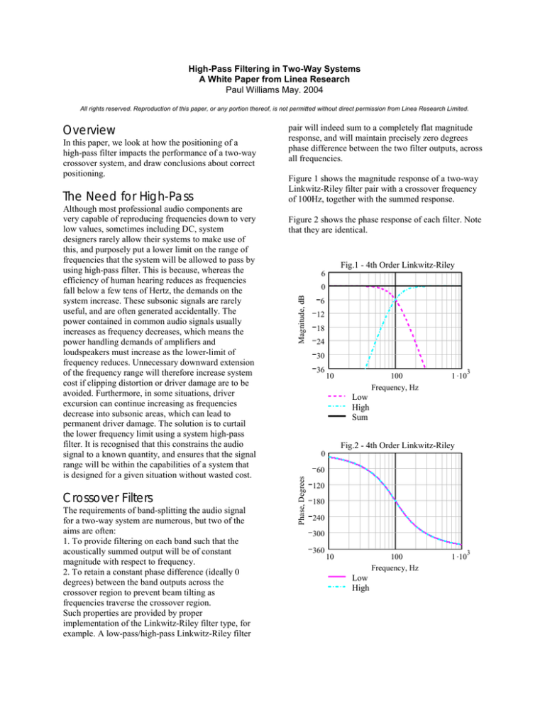
Figure 1 shows the magnitude response of a two-way
Linkwitz-Riley filter pair with a crossover frequency
of 100Hz, together with the summed response.
Figure 2 shows the phase response of each filter. Note
that they are identical.
Fig.1 - 4th Order Linkwitz-Riley
6
0
Magnitude, dB
In this paper, we look at how the positioning of a
high-pass filter impacts the performance of a two-way
crossover system, and draw conclusions about correct
positioning.
pair will indeed sum to a completely flat magnitude
response, and will maintain precisely zero degrees
phase difference between the two filter outputs, across
all frequencies.
6
12
18
24
30
36
10
100
Frequency, Hz
1 .10
3
Low
High
Sum
Fig.2 - 4th Order Linkwitz-Riley
0
60
Phase, Degrees
Overview
120
180
240
300
360
10
100
Frequency, Hz
Low
High
1 .10
3
This is plotted at the crossover frequency with driver
separation equal to the wavelength of the crossover
frequency. The scale lines are at 10 degree and 10dB
intervals. It does not take individual driver
directionality into account.
Note that the main lobe is exactly on-axis, and is
entirely symmetrical. It is important to ensure that no
phase shifts are allowed to impinge on any one band
since this will impair the accuracy of summing, and
will tilt the beam emanating from the loudspeaker
system. Such tilting will cause colouration of the
signal, and this colouration will depend on the
listening position.
Fig.3 - 4th Order Linkwitz-Riley
Adding a Fourth-order 30Hz Butterworth High-Pass
filter just to the Low band causes a phase shift on that
band, resulting in the two bands being out of phase, as
shown in Figure 4. The system no longer complies
with the Linkwitz-Riley requirements. Figure 5 shows
the resulting anomaly on the summed magnitude
response, and Figure 6 shows that the phase shift has
tipped the main lobe of the beam off-axis at the
crossover frequency, causing colouration that will
depend on the listening position. Both of these
anomalies will become worse the closer the High-pass
frequency is to the crossover frequency.
Fig.4 - With High-Pass filter
360
240
Phase, Degrees
Figure 3 shows the polar response of the system - that
is the magnitude response at different observation
angles.
120
0
120
240
360
10
100
Frequency, Hz
1 .10
3
1 .10
3
Low
High
Fig.5 - With High-Pass filter
100Hz
In active crossover devices, it is quite common for
each band to comprise both a high-pass and a lowpass crossover filter, the low-pass of the Low band
and the high-pass of the High band being used
together to form the crossover point for this two-way
system. In this configuration, the high-pass of the
Low band and the low-pass of the High band would
normally be unused, and would be bypassed. It is also
often the case that the high-pass crossover filter on
the Low band is used as a system high-pass filter.
Since the High band already has a high-pass function
due to it's crossover filter, this would seem to be a
good solution to the requirement for a system highpass filter. However, it can easily be shown that this
high-pass filtering on only the Low band causes
phase shifting of the Low band, which will cause
phase anomalies between the bands.
4
Magnitude, dB
Using Crossover Filters for System
High-Pass
6
2
0
2
4
6
10
100
Frequency, Hz
Low
High
Sum
Fig.8 - With Delay Compensation
Fig.6 - With High-Pass filter
6
Magnitude, dB
4
2
0
2
4
6
100Hz
10
100
Frequency, Hz
1 .10
3
Low
High
Sum
Compensation Using Delays
System designers may unwittingly compensate for
this anomaly when band delays are adjusted. The
high-pass filter, which introduces towards 360
degrees of phase lead at very low frequencies, still
causes a phase lead as much as 45 degrees at the
crossover frequency.
If we increase the phase lag by adding a small delay
of 1.3 milliseconds, we can correct the phase shift at
the crossover point, and thus bring the two bands inphase again. On the face of it, this seems quite
reasonable, and we can indeed see in Figure 7 that
this does correct the polar pattern, and puts the main
lobe back on-axis. However, if we look at Figure 8
we can see that the summation, whilst now correct at
the crossover point, is not quite correct either side.
Furthermore, Figure 9 shows that the polar patter
wanders off axis slightly either side of the crossover
point.
Fig.9 - With Delay Compensation
Fig.7 - With Delay Compensation
75Hz
100Hz
125Hz
100Hz
A Better Solution
A more complete solution is of course to place the
High-Pass filter in the input path so that both bands
are phase shifted identically, and will thus continue to
meet the Linkwitz-Riley requirements perfectly.
Figure 11 shows that with the High-Pass filter on the
Input, the bands sum perfectly.
former will most likely have an incorrect delay setting
on the Low band. Figure 13 shows that loudspeaker
controller parameters intended for a controller without
input high-pass filtering cause a summing anomaly if
the delay setting on the Low band is not corrected.
Figure 14 also shows that this system throws the polar
main lobe off-axis.
Figure 12 confirms that the polar response remains
rock-steady on-axis throughout the crossover region.
Fig.13 - Incorrect delay setting
6
4
Magnitude, dB
Fig.11 - High-Pass on Input
6
Magnitude, dB
4
2
0
0
2
4
2
6
4
6
2
10
100
Frequency, Hz
1 .10
10
1 .10
3
Low
High
Sum
3
Low
High
Sum
100
Frequency, Hz
Fig.14 - Incorrect Delay Setting
Fig.12 - High-Pass on Input
100Hz
75Hz
100Hz
125Hz
Parameter Conversion - A
Problem
A problem arises if it is required to take the
parameters arrived at for a Loudspeaker system
controller which uses Low band system high-pass
filtering, and apply these to a controller which uses
the more correct Input high-pass filtering, since the
Summary
We have shown that there is only one correct place to
do system high-pass filtering, and that is where there is
full-range signal, most conveniently done in the input
path of the loudspeaker system controller. Using a
spare crossover high-pass filter on the Low band will,
with some added delay, produce approximately
correct, but imperfect results. Care should be exercised
if converting parameters from a system employing
Low band high-pass filtering to a system using the
more correct Input high-pass filtering.


