Year 12 Electronics/Photonics 3
advertisement
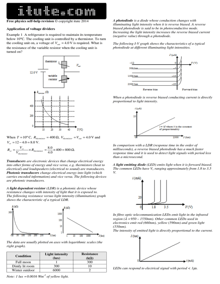
Free physics self-help revision © copyright itute 2014 Application of voltage dividers Example 1 A refrigerator is required to maintain its temperature below 10°C. The cooling unit is controlled by a thermistor. To turn the cooling unit on, a voltage of Vout = 4.0 V is required. What is the resistance of the variable resistor when the cooling unit is turned on? A photodiode is a diode whose conduction changes with illuminating light intensity when it is reverse biased. A reverse biased photodiode is said to be in photoconductive mode. Increasing the light intensity increases the reverse biased current (negative value) through a photodiode. The following I-V graph shows the characteristics of a typical photodiode at different illuminating light intensities. When a photodiode is reverse biased conducting current is directly proportional to light intensity. When T = 10° C, Rthermistor = 400 Ω, Vthermistor = Vout = 4.0 V and Vvr = 12 − 4.0 = 8.0 V. Rvr = Vvr Vthermistor × Rthermistor = In comparison with a LDR (response time in the order of milliseconds), a reverse biased photodiode has a much faster response time and it is used to detect light signals with period less than a microsecond. 8 .0 × 400 = 800 Ω. 4 .0 Transducers are electronic devices that change electrical energy into other forms of energy and vice versa, e.g. thermistors (heat to electrical) and loudspeakers (electrical to sound) are transducers. Photonic transducers change electrical energy into light (which carries encoded information) and vice versa. The following devices are photonic transducers. A light emitting diode (LED) emits light when it is forward biased. The common LEDs have Vc ranging approximately from 1.8 to 3.5 V. A light dependent resistor (LDR) is a photonic device whose resistance changes with intensity of light that it is exposed to. The following resistance versus light intensity (illumination) graph shows the characteristic of a typical LDR. In fibre optic telecommunication LEDs emit light in the infrared region (λ ≈ 950 – 1550nm). Other common LEDs used in electronics emit red (660nm), yellow (590nm) and green light (550nm). The intensity of emitted light is directly proportional to the current. The data are usually plotted on axes with logarithmic scales (the right graph). Condition Full moon Dimly lit room Winter outdoor Light intensity (lux) 1 300 6000 Note: 1 lux ≈ 0.0016 Wm-2 of yellow light. Resistance (kΩ Ω) 300 10 2 LEDs can respond to electrical signal with period < 1µs. Design and analyse electronic circuits comprising ohmic resistors, electronic and photonic transducers Non-contact switch consisting of a LDR and an ohmic resistor, e.g. in street lighting: +6 V Example 4 Refer to the characteristics of the photodiode discussed earlier. The photodiode is exposed to a time-varying light signal as shown below: J (lux) 2050 2000 1950 LDR Vo (to transistor and then street light circuitry) R 0 0.5 Sketch a graph showing Vo as a function of t. From the characteristics of the photodiode, the photodiode current is centred at 20 µA, and varies between 19.5 and 20.5 µA. .: Vo is centred at 20 × 10 −6 300 × 10 3 = 6 V, and varies between 5.85 and 6.15 V. ( 0V Example 2 Suppose the above LDR has the characteristic shown in the graph below, and street light turns on when Vo ≤ 1.5 V corresponding to light intensity ≤ 10 lux. Calculate the resistance of R to meet these requirements. t (µs) )( ) Vo (V) 6.15 6.00 5.85 0 0.5 t (µs) Light source circuit comprising a LED and an ohmic resistor: +6 V Street light turns on when outdoor light intensity (illumination) drops to 10 lux, Vo = 1.5 V, ∴V R = 1.5 V. R From graph, RLDR = 10 kΩ. VLDR = 6.0 − 1.5 = 4.5 V. V V R 1 .5 = R , R = R × RLDR = × 10 kΩ ≈ 3.3 kΩ. R LDR VLDR VLDR 4.5 LED Example 3 Refer to example 2. Should the resistance of R be higher or lower if the street light is set to turn on when outdoor light intensity drops to 8 lux? Street light is on when Vo ≤ 1.5 V, i.e. VR ≤ 1.5 V and when the outdoor light intensity is 8 lux or lower. From the given graph RLDR > 10 kΩ. V 1 .5 Since R = R × RLDR = × RLDR , when RLDR > 10 kΩ, VLDR 4 .5 R > 3.3 kΩ, i.e. higher. Light sensor comprising a photodiode and an ohmic resistor for detection of time-varying light signals of very short periods (i.e. very high frequency): +9 V photodiode 0V The emitted light intensity is directly proportional to the forward bias current through the LED. Example 5 In the above circuit the voltage across the LED is 2.0 V when it is forward biased and R = 200 Ω. (a) Calculate the forward bias current. (b) What value of R will double the intensity of light emitted? (a) VR = 6.0 − 2.0 = 4.0 V. ∴ I LED = I R = VR 4 .0 = = 0.020 A = 20 mA. R 200 (b) Since emitted light intensity is directly proportional to forward bias current through the LED, .: I LED needs to be doubled and hence R needs to be halved, i.e. 100 Ω. Vo (to CRO) 300 kΩ 0V Exercise: Next page 2011 VCAA Exam 1 2010 VCAA Exam 1 2008 VCAA Exam 1
