2011-3-Magic Motor
advertisement

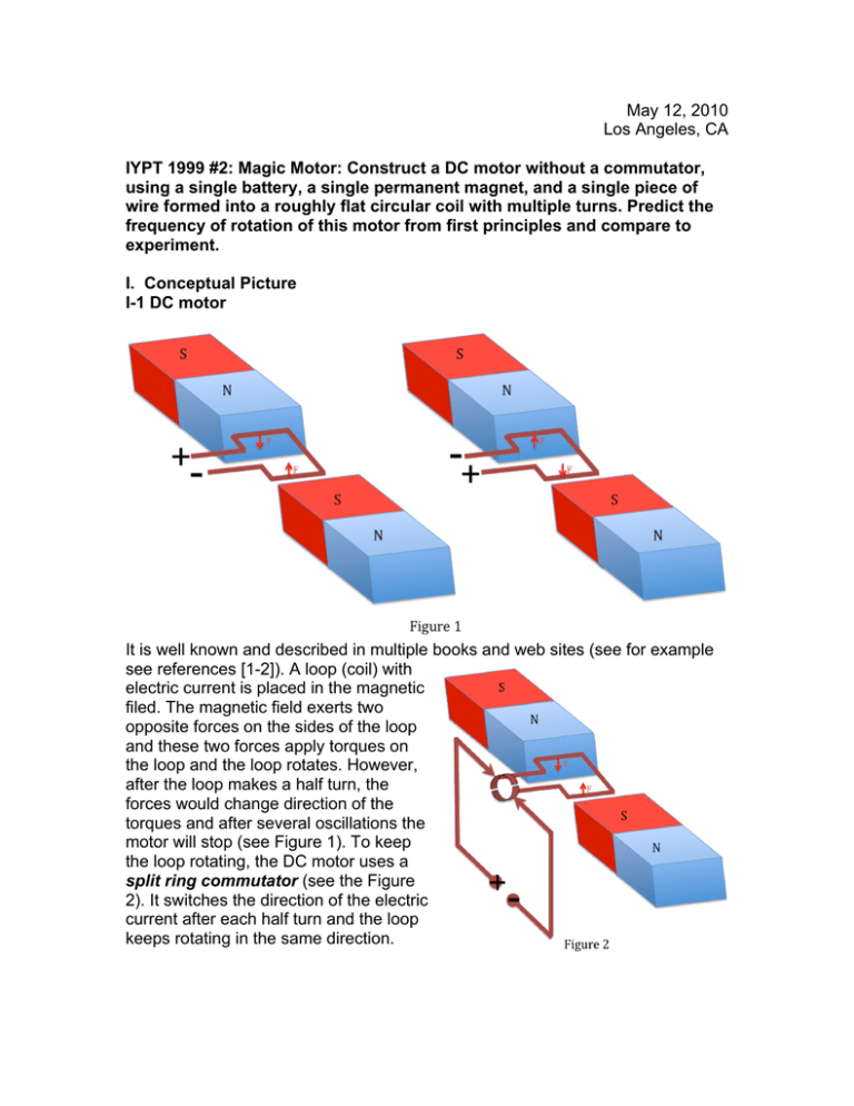
May 12, 2010 Los Angeles, CA IYPT 1999 #2: Magic Motor: Construct a DC motor without a commutator, using a single battery, a single permanent magnet, and a single piece of wire formed into a roughly flat circular coil with multiple turns. Predict the frequency of rotation of this motor from first principles and compare to experiment. I. Conceptual Picture I-1 DC motor It is well known and described in multiple books and web sites (see for example see references [1-2]). A loop (coil) with electric current is placed in the magnetic filed. The magnetic field exerts two opposite forces on the sides of the loop and these two forces apply torques on the loop and the loop rotates. However, after the loop makes a half turn, the forces would change direction of the torques and after several oscillations the motor will stop (see Figure 1). To keep the loop rotating, the DC motor uses a split ring commutator (see the Figure 2). It switches the direction of the electric current after each half turn and the loop keeps rotating in the same direction. I-2. “Magic Motor”. There is a difference between regular DC Motor and one from the problem. The “Magic motor” does not have a commutator. Figure 3 below shows the roughly flat coil of multiple turns. There is no commutator. The motor looks like the motor on Figures 1 and 2. So, you should not expect for regular motion except for small oscillations. But with some adjustments for thickness of the wire and shape you can get continuous rotation. It is magic? You can make one using different designs: as it is on the picture on the USAYPT web site [3], or with the magnet located on one or both sides from the coil rotor [4], or with the magnet and the coil rotor placed on the board which is on the table and not necessarily on top of the battery [5], or you can use your own design. You can also purchase a motor kit in the teacher supplies stores (see, fro example, [6]). If you make it as it is shown on the Figure 3, you will be surprised that it spins and it spins pretty fast. The motion does not look like oscillation at all. II. References [1] R. A. Serway, J. S. Faughn, “Holt Physics”, 2005, Holt, Rinehart and Winston [2] hyperphysics.phy-astr.gsu.edu/hbase/magnetic/motdc.html#c2 [3] www.usaypt.org [4] The Physics Teacher, Vol. 47, P. 204 [5] The Physics Teacher, Vol. 39, P. 174 [6] www.arborsci.com/prod-Worlds_Simplest_Motor-691.aspx III. Theory Hong, Choi, and Hong [4] offered the idea of the half stripped arm of the coil rotor (Figure 3). So, the coating on the opposite half will break the circuit and, therefore, will act as the commutator. This motor would work and it would look like the Magic motor, but it contains an actual commutator. Klittnick and Rickard [5] showed that it is not important to half strip the arm. Read the article where they describe an experiment and conclude that the coil rotor jumps during each rotation and “the current flows through the coil only during that portion of rotation corresponding to the time that the heavy side of the coil is at the bottom of its swing.” See Figure 4. IV. Experiment Select the thickness of the copper wire so that it does not easily bend, but is not too heavy. Use different designs to find your favorite. Reference [5] suggests using about 15 turns in the coil. The trickiest part is to estimate the time when the coil rotor jumps in your cradle and breaks the circuit. The result depends on the apparatus’ design, but the reason of why the loop jumps is the same. It happens because the center of mass of the loop is skewed from the axis of the loop’s revolution. So, the centripetal acceleration changes direction. The loop would loose contact to the support when the centripetal acceleration of the center of mass would exceed the value of the acceleration due to gravity and would be directed down. The force of normal reaction becomes equal to zero and it means that the wire lost contact with the supporting conductor. Good luck! T.Bibilashvili


