Connecting NMEA0183 to PC

Connecting instruments serially to your computer
This TechNote will review how to connect instruments (GPS, Sounder, Heading Sensor…) to a computer. Important points such as electrical specification (RS-232 vs. RS-422) and USB converter will also be reviewed.
Introduction
Instruments (GPS, Heading sensor, Sounder, AIS…) are usually connected to the computer using a serial connection. The data being transferred on that serial connection needs to be in
NMEA0183 format for the instrument(s) and computer to understand each other. Be aware that physical serial connections may be achieved using 2 different protocols: RS-232 or RS-422.
RS-232 (regular PC “COM port”)
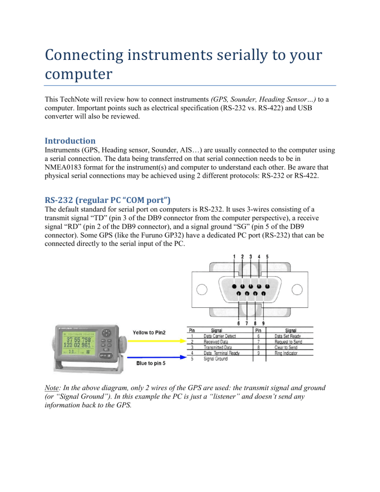
The default standard for serial port on computers is RS-232. It uses 3-wires consisting of a transmit signal “TD” (pin 3 of the DB9 connector from the computer perspective), a receive signal “RD” (pin 2 of the DB9 connector), and a signal ground “SG” (pin 5 of the DB9 connector). Some GPS (like the Furuno GP32) have a dedicated PC port (RS-232) that can be connected directly to the serial input of the PC.
Note: In the above diagram, only 2 wires of the GPS are used: the transmit signal and ground
(or “Signal Ground”). In this example the PC is just a “listener” and doesn’t send any information back to the GPS.
RS-422 (or “NMEA port”)
RS-422 uses a “balanced” (or differential) signal that does not use a common ground (“signal ground”). RS-422 uses 4 wires: TD-A (Transmit Positive), TD-B (Transmit Negative), RD-A
(Receive Positive) and RD-B (Receive Negative).
Note: “TD-A” / “TD-B” can also be noted “TD-H” / “TD-C” (Hot/Cold)
RS-422 has been selected as a preferred interface to transmit NMEA0183 data on a boat. RS-422 uses a differential signal instead of a single ended signal used by RS232. Where a single-ended system will start to become unreliable after a couple dozen feet, a differential system can be reliable for several hundreds of feet. In an electrically noisy environment like a boat, this can make a big difference. With RS-422 (differential signal), 4 wires are used (two to transmit and two to receive). Note that there is no common ground with RS-422 (no “signal ground”). The transmit and receive lines use their own “point of comparison”.
Note: Refer to the Appendix at the end of this document for more information about Differential
Signal.
All Furuno depth sounders (such as FCV620) only output NMEA0183 using the RS-422 protocol. If you want to connect the FCV620 to a serial COM port (RS232), you will have to use an RS-422 to RS-232 adapter.
BlackBox RS-232 to RS-422 converter (model IC1473A-F)
If you are using a Furuno depth sounders, connect the white wire to the RD-A (receive positive) and the black wire to the RD-B (receive negative) of the converter. In this example we do not want to talk back to the sounder (so we will not use TD-A and TD-B of the converter).
If you want to talk and listen to the NMEA0183 device, you will have to wire both TD and RD lines:
Using a Serial to USB Adapter
On most computers, the USB interface has replaced the old serial ports. Most laptop manufacturers got rid of serial ports years ago. Some desktop computers still have a serial port, but these serial interfaces are less common and it is unlikely that modern computers will have a serial port (RS-232 or RS-422). So, if you need to connect an instrument serially to your computer, you will have to purchase a Serial to USB Adapter.
Before connecting the Serial to USB Adapter, you will have to install special software (called a
“driver”) provided by the hardware manufacturer. Usually, the driver is provided on a CD, but it is always a good idea to download it from Internet (to make sure that you install the latest version). When connecting the Serial to USB Adapter to your computer, the driver will create a
“virtual COM” port. This means that for any software installed on the computer, the adapter will be seen and detected as a regular COM port (just like if the PC has a Serial COM port). Note that if the appropriate driver has not been correctly installed in Windows, the Serial to USB Adapter will not function properly and will not appear as a Virtual COM port for the software.
Here is an example of a 4 Serial Port to USB adapter. Each port can be configured either in RS-
232 or RS-422.
SeaLevel Serial to 4-Port USB Box http://cms.nobeltec.com/CMS/Products/NobeltecAccessories/AccessoriesUSB_Serial.aspx
Here is an example of a single port RS-232 Serial Port to USB adapter that can be found in most regular electronic shops:
When you purchase a Serial to USB Adapter, try to purchase one that can do either RS232 or
RS422.
USBGear DB9 Serial adapter ( www.usbgear.net
)
FAQ
Can I plug my RS-422 GPS into my computer's RS-232 Serial COM port (or RS-
232 Serial to USB adapter) and get data?
It may sometimes work... RS-232 receivers could detect the correct voltage when the negative side of the RS-422 transmitter is used as a “signal ground”. The unfortunate thing about loose adherence to RS-422 and not providing proper differential wiring is a much lower noise threshold that can introduce random “garbage” data to the line.
It is highly recommended to use a RS422 to RS232 converter whenever you have to connect a
NMEA0183 RS422 instrument to your computer. If you cannot, the following wiring might work to connect a RS422 line to an RS232 PC Serial Port:
Note: it is better to only connect one end (receive or send) according to your application (if you want to send or receive information from the PC). For example, if you want to connect a GPS, only connect TD-A of the GPS to PIN 2 of the PC and TD-B to PIN 5.
How do I know if my GPS (or instrument) is using RS-232 or RS-422?
If you count 4 wires to send and receive information from an instrument, this means that this is a
RS-422 device. Usually the RS-422 transmit line is noted on a connection diagram as “TD-
A”/“TD-B” or “TD-H”, “TD-C” and the receive line as RD-A”/“RD-B” or “RD-H”, “RD-C.
If you count only 3 wires to send and receive information, this is most likely RS-232. One wire will be named as “Ground” (“GND” or “SG”), another as “Send” (“TD”) and the last one as
“receive” (“RD”).
How to make sure that the Serial to USB adapter is detected and working correctly on my PC?
Use the Windows “Device Manager” to see if the Serial to USB Adapter created virtual COM port.
Under XP, Go to the Windows “Start” button and open Control Panel:
Open the “System” in “Control Panel.
Select the “Hardware” tab, and click on “Device Manager.”
-
Under Windows 7: Click on the “Start” button and search for “Device Manager”:
Once the “Device Manager” is opened, find and expand the “Ports (COM & LPT)” section:
The virtual COM port(s) should be listed (in this example COM5).
Troubleshooting Process:
Open the Device Manager and make sure that the Virtual COM port appears under the
“Ports (COM & LPT)” category. If they don’t appear (or if a warning appears next to it), disconnect the USB converter, make sure that the latest drivers are installed and reconnect the USB converter.
Write down the Virtual COM port number (you will need that information for the next step)
-
Open the navigation software and use the “Port Monitor” on each of the virtual COM port. Look at the NMEA sentence (ex: “$GPGGA”) to determine what type of sensor is connected (GPS, Sounder, etc…). If you see “garbage data” (random text characters), try a different Baud Rate speed (usually 4800 is used for GPS, Sounder, Heading and 38400 is used for AIS but you can occasionally have a device using something else such as
9600). Also try to revert the wire polarity. If you don’t see any data, check the wiring.
Use the Auto Detection of the navigation software to have him detect the instruments automatically or use the Manual Configuration (pointing at the Virtual COM port).
If an AIS is connected to the PC, make sure that the GPS/COG/SOG/Heading source is not set for the AIS (too slow). Use the Port Priority of Data Source selection and select the real COM port connected to the GPS, Heading…
Appendix:
How Differential Signals work and what are the advantages?
A "differential" transmission system works by transmitting over two wires (4 wires if you want to send and receive). When one wire sends a voltage, the other wire sends the opposite voltage.
The receiving side detects a transmission by comparing the voltage differential between these two transmits wires (instead of using a signal ground as in R232).
A differential setup is much less prone to inductive noise because an inducted voltage tends to affect both transmit wires in the same way. The receiving side doesn't care because it's only comparing the difference between the two wires. In other words, the inductive noise will increase
(or decrease) the voltage in both wires, but the delta (difference) between the two will remain nearly constant.


