Installation Guide — Lumination LED Luminaire Wrap
advertisement
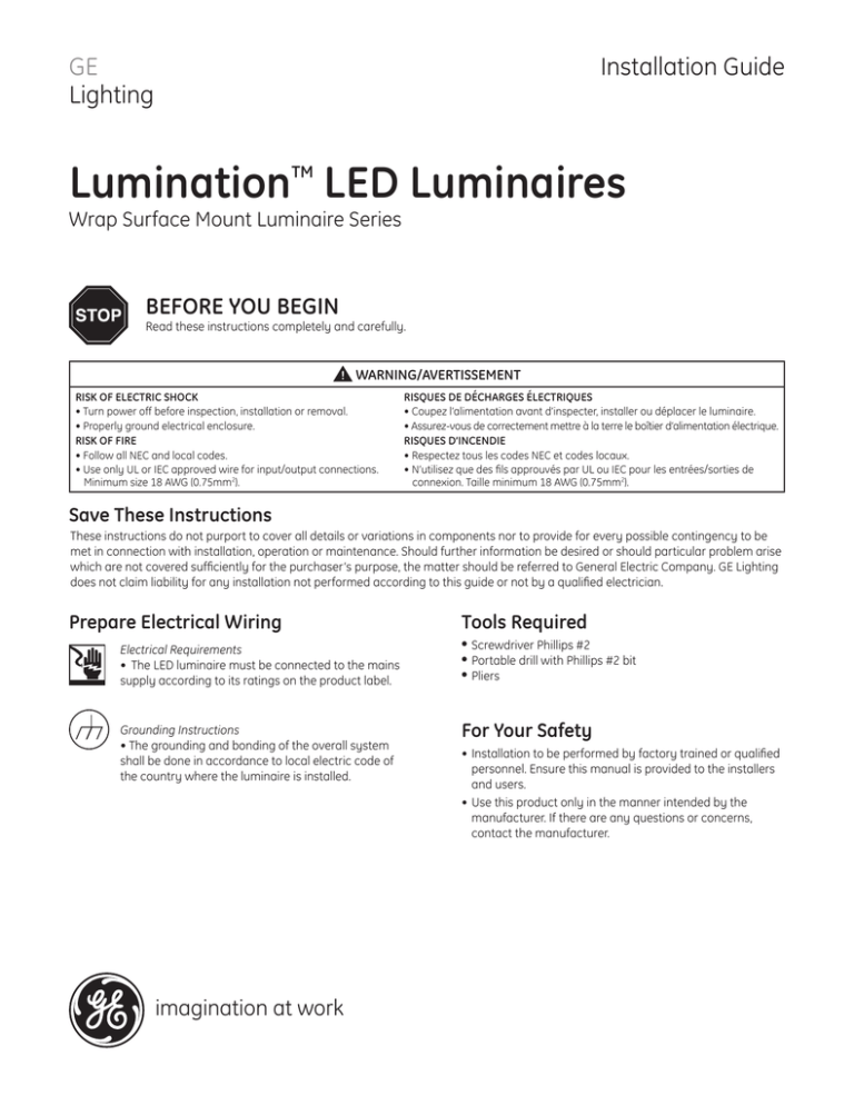
Installation Guide GE Lighting Lumination LED Luminaires TM Wrap Surface Mount Luminaire Series BEFORE YOU BEGIN Read these instructions completely and carefully. WARNING/AVERTISSEMENT RISK OF ELECTRIC SHOCK • Turn power off before inspection, installation or removal. • Properly ground electrical enclosure. RISK OF FIRE • Follow all NEC and local codes. • Use only UL or IEC approved wire for input/output connections. Minimum size 18 AWG (0.75mm2). RISQUES DE DÉCHARGES ÉLECTRIQUES • Coupez l’alimentation avant d’inspecter, installer ou déplacer le luminaire. • Assurez-vous de correctement mettre à la terre le boîtier d’alimentation électrique. RISQUES D’INCENDIE • Respectez tous les codes NEC et codes locaux. • N’utilisez que des fils approuvés par UL ou IEC pour les entrées/sorties de connexion. Taille minimum 18 AWG (0.75mm2). Save These Instructions These instructions do not purport to cover all details or variations in components nor to provide for every possible contingency to be met in connection with installation, operation or maintenance. Should further information be desired or should particular problem arise which are not covered sufficiently for the purchaser’s purpose, the matter should be referred to General Electric Company. GE Lighting does not claim liability for any installation not performed according to this guide or not by a qualified electrician. Prepare Electrical Wiring Electrical Requirements • The LED luminaire must be connected to the mains supply according to its ratings on the product label. Grounding Instructions • The grounding and bonding of the overall system shall be done in accordance to local electric code of the country where the luminaire is installed. imagination at work Tools Required •Screwdriver Phillips #2 •Portable drill with Phillips #2 bit •Pliers For Your Safety •Installation to be performed by factory trained or qualified personnel. Ensure this manual is provided to the installers and users. •Use this product only in the manner intended by the manufacturer. If there are any questions or concerns, contact the manufacturer. Installation Steps 1 2 Turn off power. Remove the driver cover. Endplate knockouts for wiring in series (optional) Attach to ceiling using 4 mounting holes shown AC line knockout 3 Dimming knockout (optional) Remove knockout for the AC line input wires. Optionally, remove additional knockouts for dimming wires and/or wiring adjacent fixtures in series. 4 Use the four existing holes in the housing to drill four fasteners (optimal for the type of ceiling present) directly into the ceiling, one fastener in each hole. This fixture may be mounted directly to the junction box if desired. Each fastener should be rated to hold at least 11 pounds. 6 Replace the driver cover. Install the lens over the housing and make sure it snaps in place securely. NOTE: If dimming wires are to be used (purple and gray wires), they must come out of a separate knockout than the line and neutral wires (white and black wires). LED driver AC line 5 Install listed electrical fittings in the knockout holes for wire protection. Connect the AC line to the black (line) and white (neutral) input wires of the LED driver using 18-14WG twist-on wire connectors. Connect the green (ground) wire to the ground screw of the housing. Important Maximum Length of Electrical Run Please see the technical data sheet for electrical properties to ensure safe installation. Under any circumstance, the maximum driver current through connected fixtures shall not exceed 16A. Refer to the table at right. Wrap Options Input Voltage Maximum Feet 2ft Narrow 120 120’ 2ft Narrow 277 265’ 2ft Wide 120 116’ 2ft Wide 277 256’ 4ft Narrow 120 190’ 4ft Narrow 277 420’ 4ft Wide 120 134’ 4ft Wide 277 305’ 4 Ft. Wiring Diagram Board interconnect wires 22” LED Board 22” LED Board 22” LED Board Line (black) Neutral (white) AC Input 22” LED Board LED Driver (Class 2) Out (+) Out (-) 0-10V (+) 0-10V (-) color? color? Dimming wire (purple) Dimming wire (gray) Ground (green) Ground screw 2 Ft. Wiring Diagram 22” LED Board Line (black) Neutral (white) AC Input 22” LED Board LED Driver (Class 2) Out (+) Out (-) 0-10V (+) 0-10V (-) color? color? Dimming wire (purple) Dimming wire (gray) Ground (green) Ground screw This device complies with Part 15 of the FCC Rules. Operation is subject to the following two conditions: (1) This device may not cause harmful interference, and (2) this device must accept any interference received, including interference that may cause undesired operation. This Class [A] RFLD complies with the Canadian standard ICES-003. Ce DEFR de la classe [ A ] est conforme à la NMB-003 du Canada. Note: This equipment has been tested and found to comply with the limits for a Class A digital device, pursuant to part 15 of the FCC Rules. These limits are designed to provide reasonable protection against harmful interference when the equipment is operated in a commercial environment. This equipment generates, uses, and can radiate radio frequency energy and, if not installed and used in accordance with the instruction manual, may cause harmful interference to radio communications. Operation of this equipment in a residential area is likely to cause harmful interference in which case the user will be required to correct the interference at his own expense. GE Lighting • 1-888-MY-GE-LED (1-888-69-43-533) • www.gelighting.com GE Lighting Solutions, LLC is a subsidiary of the General Electric Company. The GE brand, logo and Lumination are trademarks of the General Electric Company. © 2015 GE Lighting Solutions, LLC. Information provided is subject to change without notice. All values are design or typical values when measured under laboratory conditions. IND151-041015
