AKF 113S: Rotary actuator with spring return and positioner
advertisement
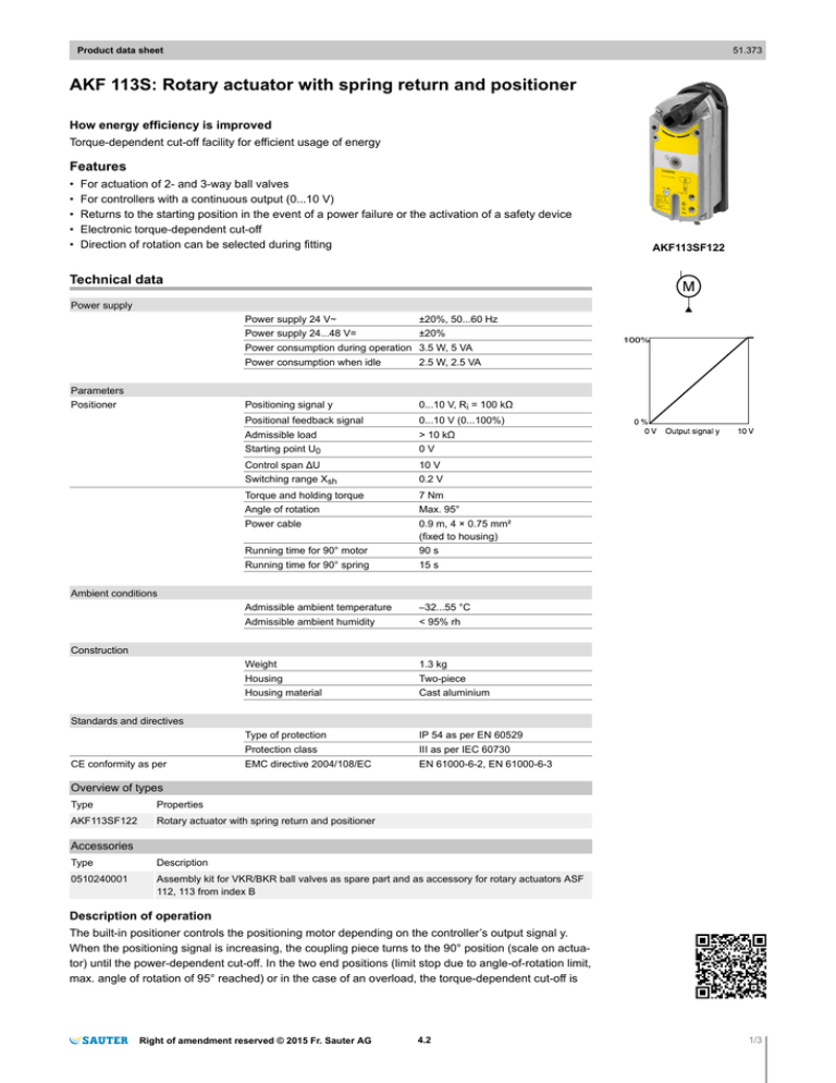
51.373 Product data sheet AKF 113S: Rotary actuator with spring return and positioner How energy efficiency is improved Torque-dependent cut-off facility for efficient usage of energy Features • • • • • For actuation of 2- and 3-way ball valves For controllers with a continuous output (0...10 V) Returns to the starting position in the event of a power failure or the activation of a safety device Electronic torque-dependent cut-off Direction of rotation can be selected during fitting AKF113SF122 Technical data Power supply Power supply 24 V~ ±20%, 50...60 Hz Power supply 24...48 V= ±20% Power consumption during operation 3.5 W, 5 VA Parameters Positioner Power consumption when idle 2.5 W, 2.5 VA Positioning signal y 0...10 V, Ri = 100 kΩ Positional feedback signal 0...10 V (0...100%) Admissible load > 10 kΩ Starting point U0 0V Control span ΔU 10 V Switching range Xsh 0.2 V Torque and holding torque 7 Nm Angle of rotation Max. 95° Power cable 0.9 m, 4 × 0.75 mm² (fixed to housing) Running time for 90° motor 90 s Running time for 90° spring 15 s Admissible ambient temperature –32...55 °C Admissible ambient humidity < 95% rh Weight 1.3 kg Ambient conditions Construction Housing Two-piece Housing material Cast aluminium Type of protection IP 54 as per EN 60529 Protection class III as per IEC 60730 EMC directive 2004/108/EC EN 61000-6-2, EN 61000-6-3 Standards and directives CE conformity as per Overview of types Type Properties AKF113SF122 Rotary actuator with spring return and positioner Accessories Type Description 0510240001 Assembly kit for VKR/BKR ball valves as spare part and as accessory for rotary actuators ASF 112, 113 from index B Description of operation The built-in positioner controls the positioning motor depending on the controller’s output signal y. When the positioning signal is increasing, the coupling piece turns to the 90° position (scale on actuator) until the power-dependent cut-off. In the two end positions (limit stop due to angle-of-rotation limit, max. angle of rotation of 95° reached) or in the case of an overload, the torque-dependent cut-off is Right of amendment reserved © 2015 Fr. Sauter AG 4.2 1/3 51.373 Product data sheet activated (no limit switches). If the power is cut off or is switched off by a safety device at connection 2 (cable = red), the motor releases the gear unit so that the spring turns the coupling piece back to the 0° position. The direction of rotation for the safety function is determined by how the actuator is mounted on the control ball valves. A signal converter is required for the reverse direction of operation. Intended use This product is only suitable for the purpose intended by the manufacturer, as described in the “Description of operation” section. All related product documents must also be adhered to. Changing or converting the product is not admissible. Engineering and fitting notes The electronic concept enables the parallel operation of multiple control ball valves with different torques. However, it must be ensured that the operating voltage is within the required tolerance range. The actuators must not be mechanically connected. The actuator can be fitted in any position apart from suspended, and can be plugged directly onto the control ball valves of types VKR and BKR and fixed by means of the mounting kit. No auxiliary switches or potentiometers can be installed subsequently. The angle of rotation can be limited to between 0° and 90° in 5° stages. Note! The housing must not be opened - risk of injury due to return spring. Additional technical data The two-part section of the housing (must not be opened) contains the brushless DC motor, the electronic control unit and the positioner, the maintenance-free gear unit with the anti-blocking function and the return spring. The actuator can be turned and locked into any position using the hex spanner supplied (see MV 505820). The gear unit is released again by unlocking it mechanically or by connecting the operating voltage. Power consumption Type Running time [s] Status Active power P [W] Apparent power S [VA] AKF113F122 90 Operation 3.5 5.0 Standstill 2.5 2.5 Outdoor installation If installed outside of buildings, the devices must be additionally protected from the weather. Disposal When disposing of the product, observe the currently applicable local laws. More information on materials can be found in the Declaration on materials and the environment for this product. Connection diagram 2/3 4.2 Right of amendment reserved © 2015 Fr. Sauter AG Product data sheet 51.373 Dimension drawing 184,7 28 64 104,3 20,5 70 84 32 Fr. Sauter AG Im Surinam 55 CH-4016 Basel Tel. +41 61 - 695 55 55 www.sauter-controls.com Right of amendment reserved © 2015 Fr. Sauter AG 4.2 3/3

