APPLICATION GUIDE
Type DV e-Rated® Distribution TransFilter™
Ultra-Efficient, Low Voltage, Dry-Type Isolation Transformer
for High K-Factor, Phase-to-Neutral Connected Nonlinear Loads
Product Description
Type DV e-Rated® low voltage dry-type isolation transformers provide ultraefficient alternatives to conventional or K-Rated distribution transformers.
Type DV transformers are ideally suited for new construction or the
replacement of older transformers with historically low efficiencies as part of
a power system optimization and energy reduction plan.
Table 1
Required vs. PQI Energy Efficiencies [1]
kVA
Rating
NEMA
TP 1 2002 [2]
CSA C802.2
15
30
45
75
112.5
150
225
300
500
750
1000
97.00
97.50
97.70
98.00
98.20
98.30
98.50
98.60
98.70
98.80
98.90
Efficiency
With reference to Table 1, Type DV e-Rated® transformers, with standard
‘Z3’ efficiencies, exceed the energy efficiency requirements of NEMA TP 12002, CSA C802.2-12, NEMA Premium™, US DOE Candidate Standard
Levels (CSL) 3 and 4 and pending US DOE 2016 levels. With reference to
the table, optional ‘Z3+’ and ‘Z4’, with progressively higher levels of energy
efficiency, are also available.
Efficiency Confirmation
The efficiencies of Type DV e-Rated® transformers are confirmed using
NEMA TP 2-2005 (Standard Test Method for Measuring the Energy
Consumption of Distribution Transformers). If necessary these results can be
subjected to CSA C802.5 (Guide for Selection of Efficient Dry-Type
Transformers for Nonlinear Loading) calculations to determine their nonlinear
efficiencies, at any load level, with any defined or measured harmonic current
profile.
kVA Sizing and Efficiency Considerations for New Construction
A Load Factor survey, undertaken by The Cadmus Group Inc.in 1999, found
that the average loading of low voltage dry-type distribution transformers in
commercial, industrial and public buildings was in a range between 9% and
17% of their full load ratings. They also found that loading, for at least 12
hours a day, was only 10% of the average. More recent surveys have shown
much lower Load Factors, the result of upgrading to more energy efficient
loads.
Transformer oversizing is a typical outcome when meeting the requirements
of national and local electrical codes in the USA and Canada. Selecting the
optimum transformer kVA can be determined by referring to CSA Standard
C802.4-13 (Guide for kVA Sizing of Dry-Type Transformers).
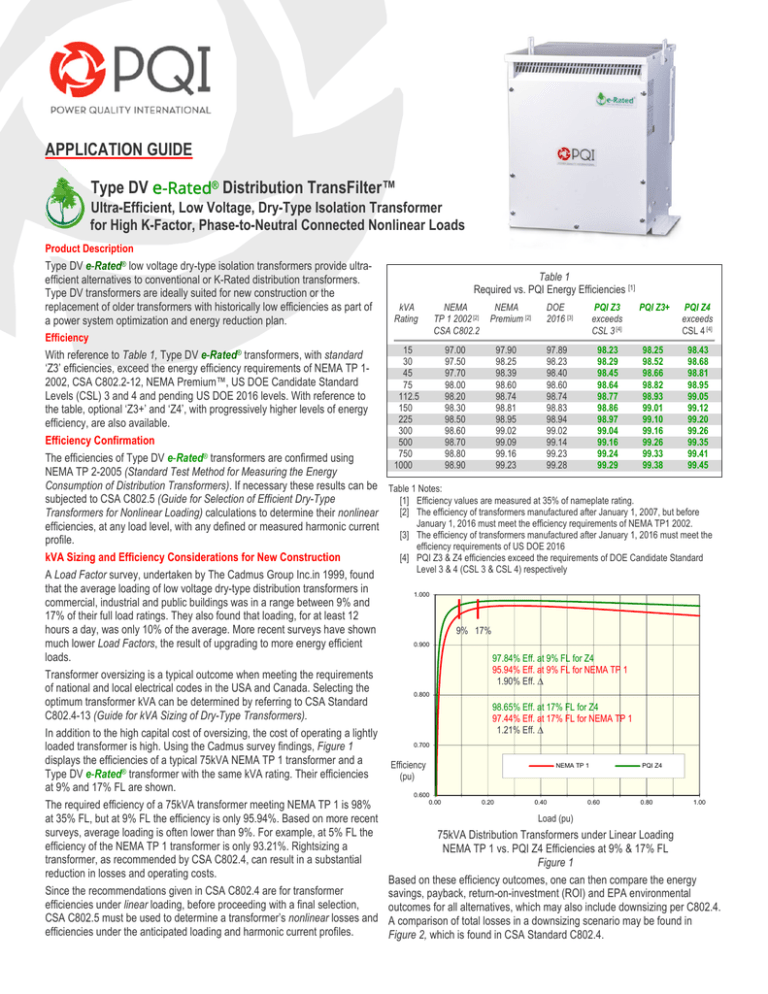
In addition to the high capital cost of oversizing, the cost of operating a lightly
loaded transformer is high. Using the Cadmus survey findings, Figure 1
displays the efficiencies of a typical 75kVA NEMA TP 1 transformer and a
Type DV e-Rated® transformer with the same kVA rating. Their efficiencies
at 9% and 17% FL are shown.
The required efficiency of a 75kVA transformer meeting NEMA TP 1 is 98%
at 35% FL, but at 9% FL the efficiency is only 95.94%. Based on more recent
surveys, average loading is often lower than 9%. For example, at 5% FL the
efficiency of the NEMA TP 1 transformer is only 93.21%. Rightsizing a
transformer, as recommended by CSA C802.4, can result in a substantial
reduction in losses and operating costs.
Since the recommendations given in CSA C802.4 are for transformer
efficiencies under linear loading, before proceeding with a final selection,
CSA C802.5 must be used to determine a transformer’s nonlinear losses and
efficiencies under the anticipated loading and harmonic current profiles.
NEMA
Premium [2]
97.90
98.25
98.39
98.60
98.74
98.81
98.95
99.02
99.09
99.16
99.23
DOE
2016 [3]
PQI Z3
exceeds
CSL 3 [4]
PQI Z3+
PQI Z4
exceeds
CSL 4 [4]
97.89
98.23
98.40
98.60
98.74
98.83
98.94
99.02
99.14
99.23
99.28
98.23
98.29
98.45
98.64
98.77
98.86
98.97
99.04
99.16
99.24
99.29
98.25
98.52
98.66
98.82
98.93
99.01
99.10
99.16
99.26
99.33
99.38
98.43
98.68
98.81
98.95
99.05
99.12
99.20
99.26
99.35
99.41
99.45
Table 1 Notes:
[1] Efficiency values are measured at 35% of nameplate rating.
[2] The efficiency of transformers manufactured after January 1, 2007, but before
January 1, 2016 must meet the efficiency requirements of NEMA TP1 2002.
[3] The efficiency of transformers manufactured after January 1, 2016 must meet the
efficiency requirements of US DOE 2016
[4] PQI Z3 & Z4 efficiencies exceed the requirements of DOE Candidate Standard
Level 3 & 4 (CSL 3 & CSL 4) respectively
1.000
I I
9% 17%
0.900
97.84% Eff. at 9% FL for Z4
95.94% Eff. at 9% FL for NEMA TP 1
1.90% Eff. ∆
0.800
98.65% Eff. at 17% FL for Z4
97.44% Eff. at 17% FL for NEMA TP 1
1.21% Eff. ∆
0.700
Efficiency
(pu)
0.600
0.00
NEMA TP 1
0.20
0.40
0.60
PQI Z4
0.80
1.00
Load (pu)
75kVA Distribution Transformers under Linear Loading
NEMA TP 1 vs. PQI Z4 Efficiencies at 9% & 17% FL
Figure 1
Based on these efficiency outcomes, one can then compare the energy
savings, payback, return-on-investment (ROI) and EPA environmental
outcomes for all alternatives, which may also include downsizing per C802.4.
A comparison of total losses in a downsizing scenario may be found in
Figure 2, which is found in CSA Standard C802.4.
Type ‘DV’ e-Rated® Ultra-Efficient, Low Voltage, Dry-Type, Distribution TransFilters™
3.0
Total Losses (W)
Total Losses vs Load for Different Sized Three Phase Transformers
with Losses Optimized to meet CSA C802.2‐12 (up to 50 kVA Load)
75kVA NEMA TP 1
30kVA PQI Z4
2.5
1800
1600
1400
1200
1000
800
600
400
200
0
2.0
1.5
Losses
kW
75kVA
1.0
0
5
10
15
20
25
30
35
40
45
50
Load (kVA)
0.5
15
30
45
75
112.5
150
225
300
500
750
2855W
1000
1863W ∆
I
992W
30kVA
I
Graph taken from CSA C802.4
0.0
0
0.1
0.2
0.3
0.4
0.5
0.6
0.7
0.8
0.9
1
Standard for kVA Sizing of Dry-Type Transformers
Load (pu)
Figure 2
75kVA
&
30kVA
Distribution
TransFilters™ Losses
With reference to the Figure 2, using the 9% and 17% load levels described
75kVA
NEMA
TP
1
vs.
30kVA
PQI
Z4
under 6.75kVA Linear Loading
in Figure 1, one can examine the ‘rightsizing’ possibilities. For example, if a
Figure 3
75kVA transformer was initially considered, but the anticipated load was only
1.000
9% FL or 6.75kVA, the best alternative may be a 30kVA transformer with an
I
average equivalent load of 22.5% FL. Based on the graph a 15kVA unit at
98.54%
I
45% FL may also qualify since its calculated average Load Factor would not
95.94%
2.6% ∆
exceed 50% FL, a nationalgrid® transformer replacement program
0.900
recommendation. Before proceeding with this alternative, however, one must
consider the possible addition of future loads.
Applying the same logic, if a 75kVA transformer was initially considered, but
0.800
the anticipated load was only 17% FL or 12.75kVA, a 45kVA unit at 28.33%
FL or a 30kVA unit at 42.50% FL could be considered.
Based on the 75kVA, 9% FL average load example, Figures 3 & 4 detail the Efficiency
(pu)
differences in losses and efficiencies when comparing the 75kVA vs. 30kVA
0.700
transformers. With 1863W lower losses and 2.6% higher efficiency, the
30kVA ultra-efficient transformer will provide significant energy savings.
75kVA NEMA TP 1
30kVA PQI Z4
kVA Sizing and Efficiency Considerations when Replacing Existing
0.600
Transformers
0.00
0.20
0.40
0.60
0.80
1.00
The motivation to replace an existing transformer is usually based on its
Load (pu)
questionable reliability and/or a need to reduce energy consumption and
75kVA & 30kVA Distribution TransFilters Efficiency
cost. Based again on the Load Factor survey undertaken by The Cadmus
75kVA NEMA TP 1 vs. 30kVA PQI Z4 under 6.75kVA Linear Loading
Group, the higher excitation losses and lower efficiencies of pre-NEMA TP 1
Figure 4
transformers, particularly at low Load Factors, provides an even greater
opportunity to save energy and reduce operating costs.
1.000
I
As demonstrated in Figure 5, at 9% FL the efficiency of the pre-NEMA TP 1
98.54%
transformer is only 92.84%. Based on more recent surveys, average loading
I
5.7% ∆
is often much lower. At 5% FL the efficiency of the pre-NEMA TP 1 unit is
0.900
only 88.11%. Rightsizing a transformer, as recommended in CSA C802.4
92.84%
and the nationalgrid® Transformer Replacement Program for Low-Voltage
Dry-Type Transformers program, can result in a substantial reduction in
0.800
operating costs.
The nationalgrid® program recommends that downsizing should only be
Efficiency
(pu)
considered if:
0.700
1. The measured Load Factor of the existing transformer never
exceeds 35% FL or
75kVA Pre-NEMA TP 1
30kVA PQI Z4
2. The calculated Load Factor of the replacement transformer never
0.600
exceeds 50% FL.
0.00
0.20
0.40
0.60
0.80
1.00
Based on these criteria, the Load Factor for the replacement transformer can
Load (pu)
be calculated as follow:
75kVA & 30kVA Distribution TransFilters Efficiency
LFNEW = LFOLD x (kVAOLD / kVANEW)
75kVA Pri-NEMA TP 1 vs. 30kVA PQI Z4 under 6.75kVA Linear Loading
Figure 5
To determine the replacement transformer’s potential energy savings,
payback, ROI and EPA environmental outcomes, CSA C802.5 must first be
POWER QUALITY INTERNATIONAL, LLC
used to calculate the efficiency of the existing and proposed replacement
transformers, under their measured or calculated Load Factors. At low Load
Factors the national electrical codes are somewhat more flexible regarding
downsizing, if the load profiles can be confirmed. Since even an ultra-efficient
transformer’s efficiency begins to fall off below 15% FL, downsizing with a
smaller, more efficient transformer will also provide an attractive capital cost
reduction.
High K-Factor Nonlinear Loading
Type DV Distribution TransFilters’ ultra-low zero-sequence impedances
effectively reduce voltage distortion (THDV) at their subsystem’s loads, the
principal cause of reduced load efficiency. Type DV transformers can often
be applied as ‘standalone’ harmonic mitigating solutions or in combination
with Type Z I0Filters™ and/or ‘Mini-Z™ (zero-sequence harmonic shunt
filters). Type DV transformers are available with optional primary-tosecondary phase-shifts, allowing the system designer to create 12-, 18- or
24-pulse harmonic current profiles at a common primary bus. Progressively
high pulse-numbers will reduce harmonic current related ‘penalty losses’ in
the primary system and improve system Power Factor.
Type DV transformers are ideally suited for new construction or the
replacement of older transformers with historically low efficiencies as part of
a power system optimization and energy reduction plan.
Product Application
The benefits of a Distribution TransFilter™ application are optimized when
these devices are installed as close as possible to the sources of positive-,
negative- and zero-sequence harmonic currents. This is typically
accomplished by installing the transformer in close proximity to the threephase, four-wire panel that supplies single-phase, nonlinear loads.
The determination of preferred Distribution TransFilter™ types, locations and
ratings will be demonstrated in the following examples:
Case 1
With reference to Figure 6, the 120/208V Subsystem 1 includes a Type DV0 Distribution TransFilter™, with a primary-secondary phase-shift of 0° @
60Hz, while the 120/208V Subsystem 2 includes a Type DV30 - Distribution
TransFilter™, with a primary-secondary phase-shift of -30° @ 60Hz. The
secondary outputs from these transformers are therefore 30° out-of-phase.
Each of these transformers is connected to its panel via a 3Ø, 4W circuit.
current, in order to create a 180° phase-shift at that
frequency which will result in its cancellation.
H
- The harmonic number of the particular harmonic
frequency.
In order to achieve the maximum benefit, it is normal practice to select the
second order, zero-sequence harmonic frequency that separates the positive
and negative frequencies to be cancelled. This method results in a significant
reduction of both targeted harmonic currents.
As an alternative to the above, and again with reference to Figure 6, the
120/208V Subsystem 1 includes a Type DV0 - Distribution TransFilter™, with
a primary-secondary phase-shift of 0° @ 60Hz, while a preexisting 120/208V
Subsystem 2 includes a conventional Delta-Wye Distribution Transformer,
with a primary-secondary phase-shift of -30° @ 60Hz. The secondary
outputs from these transformers are, therefore, 30° out-of-phase as before.
Each of these transformers is connected to its panel via a 3Ø, 4W circuit.
Again, all of the system improvements listed under PRODUCT
DESCRIPTION will accrue to Subsystem 1 while many improvements will
also accrue to Subsystem 2.
As an alternative, the Distribution TransFilter™ may be installed at some
distance from the sources of positive-, negative- and zero-sequence
harmonic currents when the installation includes the application of an
I0Filter™ - Zero Sequence Harmonic Filter(s). This may be the only
alternative when the Distribution TransFilter™ has high kVA ratings and the
120/208V subsystem includes multiple panels and/or sub-panels. In this
case, a filter(s) may be required at each remote three-phase, four-wire subpanel that supplies single-phase, non-linear loads. Detail on the application
of I0Filters™may be found in the Type Z - APPLICATION GUIDE.
The determination of preferred Distribution TransFilter™ and I0Filter™
locations and ratings will be demonstrated in the following examples:
Case 2
With reference to Figure 7, the 120/208V Subsystem 1 includes a Type DV0 Distribution TransFilter™, with a primary-secondary phase-shift of 0°@
60Hz, while 120/208V Subsystem 2 includes a Type DV30 - Distribution
TransFilter™, with a primary-secondary phase-shift of -30° @ 60Hz. The
secondary outputs from these transformers are, therefore, 30° out-of-phase.
Each of these transformers is connected to its panel(s) via a 3Ø, 4W circuit.
TX1
480 V
TX1
120/208 V
SUBSYSTEM 1
480 V
TYPE DZ
PANEL
SUBSYSTEM 1
(REMOTE LOCATION)
PANEL
1
TYPE DV0 75
TX2
480 V
120/208 V
PANEL
2
TX2
120/208 V
TYPE DV
OR
[DELTA-WYE ALTERNATIVE]
SUBSYSTEM 2
480 V
PANEL
TYPE DV30 75
120/208 V
SUBSYSTEM 2
150 A
I0FILTER
PANEL
Figure 7
If we now assume that the three panels will be used to supply single-phase,
nonlinear loads, then the 5th, 7th, 17th, 19th --- positive- and negativesequence harmonic currents, generated by the loads connected to each
Distribution TransFilter™, will be out-of-phase by 30° @ 60Hz or
approximately 180° at each targeted harmonic frequency. As a result, most
of these particular harmonic currents will cancel on the transformers’
common primary bus.
If we also assume that each panel in Subsystem 1 will be used to supply
30kVA ([75kVA x 0.8]/2) of single-phase nonlinear loads exclusively, then a
° @ 60Hz = 180° @ 60Hz / H
[1]
150A I0Filter™ should be installed at Panel 2. The zero-sequence harmonic
where:
currents, generated by the loads connected to Panel 1, will be shunted by the
Type DV0 - Distribution TransFilter™(TX1). The installations must be in
° @ 60Hz - The exact phase-shift @ 60Hz which is required,
between two separate sources of a particular harmonic accordance with the appropriate I0Filter™ - Connection Diagram.
Figure 6
If we assume that the two panels will be used to supply single-phase,
nonlinear loads, then the 5th, 7th, 17th, 19th --- positive- and negativesequence harmonic currents, generated by the loads connected to each
panel, will be out-of-phase by 30° @ 60Hz or approximately 180° at each
targeted harmonic frequency. As a result, most of these particular harmonic
currents will cancel on the transformers’ common primary bus.
Under these conditions, the exact phase-shift, which is required to cancel any
particular harmonic frequency, would be as follows:
Product Application Alternatives
In the event that a 480V bus supplies three or more Distribution
TransFilters™, other phase-shifting angles may be chosen in order to cancel
additional positive- and negative-sequence harmonic currents. For example,
if three (groups of) transformers (≈equal kVA) are installed, Types DV10,
DV30 and DV50 can be applied in order to cancel the 5th, 7th, 11th, 13th,
17th, 19th, --- positive- and negative-sequence harmonic currents.
Alternatively, if four (groups of) transformers (≈ equal kVA) are installed,
Types DV0, DV15, DV30 and DV45 can be applied in order to cancel the 5th,
7th, 11th, 13th, 17th, 19th, 23rd, 25th, --- positive- and negative-sequence
harmonic currents.
The PQI Solution™
Power Quality International uses IEEE Std. C57.110 and CSA C802.5
compliant engineering software to quickly and accurately compare the losses
and efficiencies of any two transformers, under any anticipated or measured
harmonic and loading profile. Given the cost of each transformer, or a single
transformer in a replacement scenario, and utility rates, the software also
calculates the annual energy savings, including A/C costs, payback on
incremental or replacement costs, return-on-investment and EPA
environmental benefits.
PQI’s Application Engineers can also develop a harmonic mitigation plan that
will reduce the system’s ‘penalty losses’ and ensure that voltage distortion at
the loads will not exceed 5% THDV, an IEEE Std. 519-1992 recommendation.
PQI offers these analytical services, with recommendations, on a ‘no charge’
basis. To access this service, please contact PQI at (888) 539-7712 or
engineering@PowerQualityInternational.com.
All Specifications are subject to change without notice.
All contents © 2014, Power Quality International, LLC, All Rights Reserved.
e-Rated®
POWER QUALITY INTERNATIONAL, LLC
2404 Merchant Ave., Odessa, Florida 33556
Office (888) 539-7712 ● Fax (727) 478-7289 ● Web www.powerquality.net


