First-Order Circuits
advertisement

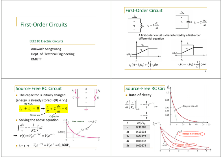
First-Order Circuit First-Order Circuits vL = L iC = C diL dvC dt dt A first-order circuit is characterized by a first-order differential equation EEE110 Electric Circuits Anawach Sangswang Dept. of Electrical Engineering KMUTT iL (t ) = iL (t1 ) + 1 t ∫ vL dσ L t1 vc (t ) = vc (t1 ) + 1 t ∫ ic dσ C t1 2 Source-Free RC Circuit Source-Free RC Circuit Rate of decay The capacitor is initially charged (energy is already stored v(0) V0) d v 1 −t / τ =− e t =0 τ dt V0 t =0 By KCL iR + iC = 0 Ohms law dv v +C =0 dt R =− Capacitor Solving the above equation Time constant τ=RC dv 1 = − ∫ v RC ∫ dt v(t ) = V0 e −t / RC = V0 e −t / τ t=τ V0 e − t / τ = V0 e −1 = 0.368V0 3 t τ 2τ 3τ 4τ 5τ 1 τ v(t)/V0 0.36788 0.13534 0.04979 0.01832 0.00674 Decays more slowly Decays faster 4 Source-Free RC Circuit Example 7.1 The natural response of a circuit = the behavior (in terms of voltages and currents) of the circuit itself, with no external sources of excitation The time constant τ of a circuit is the time required for the response to decay by a factor of 1/e or 36.8% of its initial value. v decays faster for small τ and slower for large τ The key to working with a source-free RC circuit is finding: The initial voltage v(0) = V0 across the capacitor. The time constant τ = RC. Let vC(0) = 15V. Find vC , vx and ix for t> 0 τ = Req C = 0.4 s Req = 5 × 20 = 4Ω 5 + 20 v = vC = v( 0 )e− t / τ = 15e− t / 0.4 = 15e −2.5t vx , voltage divider ix vx = 12 15e −2.5t = 9e−2.5t 12 + 8 ix = vx = 0.75e−2.5t 12 5 Example 7.2 6 Source-Free RL Circuit A first-order RL circuit consists of an inductor L (or its equivalent) and a resistor R (or its equivalent) The switch is open at t = 0 Find v(t) for t ≥ 0, and the initial energy stored in the capacitor t < 0, 9 vC = 20 = 15V 3+9 By KVL vL + v R = 0 L di + iR = 0 dt t > 0, Req = 9 + 1 = 10Ω Inductors law τ = Req C = 10 × 20 ×10−3 = 0.2 s Solving for i(t) v( t ) = v( 0 )e − t / τ = 15e − t / 0.2 = 15e −5t Initial energy 1 wC ( 0 ) = CvC2 ( 0 ) = 2.25 J 2 Ohms law i (t ) 7 t di R = − ∫i (0) i ∫0 L dt ln i (t ) − ln i (0) = − Rt +0 L 8 Source-Free RL Circuit Source-Free RL Circuit The key to working with a source-free RL circuit is finding: A general form representing RL i(t ) = I 0 e − t / τ i (t ) = I 0 e −t /τ L where τ = R The time constant τ of a circuit is the time required for the response to decay by a factor of 1/e or 36.8% of its initial value. i(t) decays faster for small τ and slower for large τ The general form is very similar to a RC source-free circuit. where τ = L R The initial voltage i(0) = I0 through the inductor. The time constant τ = L/R 9 Example 7.3 Find i, ix i (0) = 10 1) Equivalent resistance 10 Example 7.3 2) Solving the differential equation Loop1 di1 1 di1 + 2(i1 − i2 ) = 0 + 4i1 − 4i2 = 0 dt 2 dt di1 2 + i1 = 0 dt 3 5 i2 = i1 6 2(i1 − i2 ) + 1 = 0 i1 − i2 = − 6i2 − 2i1 − 3i1 = 0 5 i2 = i1 1 2 i1 = −3 A i (t ) 1 t di 2 ∫i (0) i11 = − 3 ∫0 dt io = −i1 = 3 A 6 3 = 2= Req = RTh = = ,τ = L Req 1 2 io 3 3 vo 1 Loop2 6i2 − 2i1 − 3i1 = 0 Rearrange and integrate both sides 2 t i (t ) ln i i (0) = − t 0 i (t ) = i (0)e− t /τ = 10e −2t / 3 3 The inductor voltage i (t ) = i (0)e− t /τ = 10e −2t / 3 11 vL = L di 2 10 = 0.5 ×10 × − e −2t / 3 = − e −2t / 3 dt 3 3 ix = vL 5 = − e −2t / 3 2 3 12 Example 7.5 Comparison between a RL and RC circuit Find io, vo, i t<0 10 i (t ) = = 2 A, vo = 3i (t ) = 6V 2+3 io = 0 t>0 A RL source-free circuit A RC source-free circuit L R v(t ) = V0 e − t /τ where τ = RC i (t ) = I 0 e − t / τ where τ= RTh = 3 6 = 2Ω, τ = L / RTh = 1 i (t ) = i (0)e −t /τ = 2e −t A di v0 (t ) = −vL = − L = 4e −tV dt v 2 i0 (t ) = L = − e −t A 6 3 Singularity Singularity (or switching) functions are functions that either discontinuous or have discontinuous derivatives The unit step function u(t) is 0 for negative values of t and 1 for positive values of t. 0, u (t − to ) = 1, t < to t > to 0, u (t ) = 1, 13 14 Unit Step Function t<0 t>0 Representation on a circuit Voltage source Current source 0, u (t + to ) = 1, t < − to t > − to Unit impulse function (delta function) t <0 0, d δ (t ) = u(t ) = undefined t = 0 dt 0, t >0 15 16 Unit Impulse Function Example 7.6 Properties Mathematically express the given signal & its derivative Not physically realizable It is a very short duration pulse of unit area and can be 0+ expressed as ∫ 0− δ (t )dt = 1 The unit area is known as the strength of the impulse function dv = 10 [δ (t − 2) − δ (t − 5)] dt Sampling property ∫ b a b f (t )δ (t − t0 )dt = ∫ f (t0 )δ (t − t0 )dt v(t ) = 10u(t − 2) − 10u(t − 5) a = 10 [u(t − 2) − u(t − 5)] b = f (t0 )∫ δ (t − t0 )dt = f (t0 ) a ∫ b a f (t )δ (t − t0 )dt = f (t0 ) 17 Step Response: RC Circuit Step Response: RC Circuit The step response of a circuit is its behavior when the excitation is the step function, which may be a voltage or a current source. Rearrange and integrate both sides ∫ v (t ) V0 • Initial condition: t dt dv = −∫ 0 RC v − Vs ln ( v − Vs ) − ln (V0 − Vs ) = − Combine and take the exponential v − Vs −t = e RC = e−t /τ , τ = RC V0 − Vs v(0-) = v(0+) = V0 • Applying KCL, Uncharged capacitor (V0 = 0) dv v − Vs u (t ) C + =0 dt R or 18 v(t ) = Vs (1 − e−t /τ ) i(t ) = C t RC Complete response ,t <0 V0 v= −t /τ Vs + (V0 − Vs )e , t > 0 dv Vs −t /τ = e dt R dv v − Vs =− u (t ) dt RC • Where u(t) is the unit-step function 19 20 Step Response: RC Circuit Step Response: RC Circuit Integrating both sides and considering the initial conditions, the solution of the equation is: Complete Response = Initial value at t = 0 Natural response (stored energy) = V0e–t/τ + + vn Complete Response t<0 V0 v(t ) = −t / τ Vs + (V0 − Vs )e Final value at t -> ∞ Another way of looking at it t >0 Source-free Response = ( V0 - Vs)e–t/τ + steady-state response (permanent) + Vs Typical form The initial capacitor voltage v(0) The final capacitor voltage v(∞) — DC voltage across C The time constant τ. Note: if the switch operates at time t = t0, the form becomes v (t) = v (∞) + [v (t0 ) − v (∞)] e−(t−t0 )/τ Vs(1–e–t/τ) 21 22 Step Response: RL Circuit Example 7.10: v(t) The step response of a circuit is its behavior when the excitation is the step function, which may be a voltage or a current source. Find v(t) @ t = 1s, 4s t < 0: switch @A v(0− ) = transient response (temporary) v (t) = v (∞) + [v (0+) − v (∞)]e−t /τ To determine the step response of an RC circuit: Forced Response (independent source) vf = 5 × 24 = 15V 5+3 • Initial current i(0-) = i(0+) = Io • Final inductor current i(∞) = Vs/R • Time constant τ = L/R t > 0: switch @B, v(0) = v(0-) = v(0+) τ = RThC = 4k Ω⋅ 0.5mF = 2s From circuit, v(∞) = 30V v(t ) = v(∞) + [ v(0) − v(∞)] e−t /τ = 30 + (15 − 30)e−t / 2 = 30 − 15e−.5tV −0.5 At t = 1, v(1) = 30 − 15e = 20.9V At t = 4, v(4) = 30 − 15e−2 = 27.97V 23 i = itransient + isteady −state V τ = L/ R i = Ae−t /τ + s R V • At t = 0, I0 = A + s R V V i = I 0 − s e− t /τ + s R R I0 = 0 24 Step Response: RL Circuit Example 7.12: i(t), t > 0 t<0 V V i = I 0 − s e− t /τ + s R R i(0− ) = 10 = 5A 2 i(0) = i(0− ) = i(0+ ) t>0 i (t ) = i (∞) + [i (0+ ) − i (∞)] e − t /τ i(∞) = 10 = 2 A, RTh = 2 + 3 = 5Ω 2+3 τ = L / RTh = 1/15 Three steps to find out the step response of an RL circuit: −t /τ −15t The current i(t ) = i(∞) + [i(0) − i(∞)] e = 2 + 3e Check: KVL The initial inductor current i(0) at t = 0+ The final inductor current i(∞) The time constant τ Note: This technique applies only for the step responses −10 + 5i + 25 1 di =0 3 dt 1 −10 + 5(2 + 3e−15t ) + (3 × −15e−15t ) = 0 3 26


