Application Note 1978
Surge Protection for Intersil's Standard RS-485
Transceivers
Introduction
This application note presents various protection methods for
Intersil's standard RS-485 transceivers.
AN1977 explained, connecting TVS devices directly to the
transceiver bus terminals introduces the risk of damaging the
transceiver's ESD structures during a surge event. Adding
current limiting components in series with the bus terminals
lowers the risk. In doing so, the type and number of
components being added depends on the surge protection
level required for the application. Refer to AN1976, “Important
Transient Immunity Tests for RS-485 Networks” for the
assignment of protection levels to specific installation classes.
To limit the bus currents into the transceiver during a surge
event, carbon composite or pulse-proof thick-film resistors
should be inserted between the TVSs and the transceiver. Due
to their voltage divider action with the bus termination
resistors, their value should be 10Ω or less to minimize bus
voltage attenuation during normal operation.
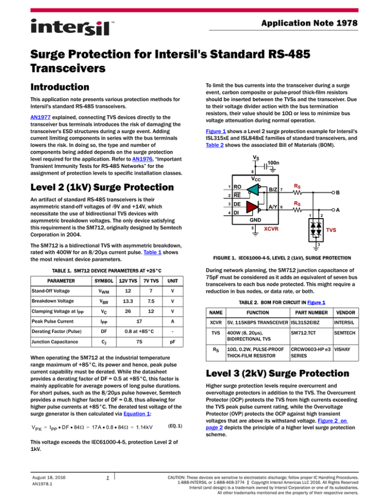
Figure 1 shows a Level 2 surge protection example for Intersil's
ISL315xE and ISL848xE families of standard transceivers, and
Table 2 shows the associated Bill of Materials (BOM).
VS
8
VCC
Level 2 (1kV) Surge Protection
An artifact of standard RS-485 transceivers is their
asymmetric stand-off voltages of -9V and +14V, which
necessitate the use of bidirectional TVS devices with
asymmetric breakdown voltages. The only device satisfying
this requirement is the SM712, originally designed by Semtech
Corporation in 2004.
The SM712 is a bidirectional TVS with asymmetric breakdown,
rated with 400W for an 8/20µs current pulse. Table 1 shows
the most relevant device parameters.
100n
1
RO
2
RE
3
DE
4
DI
B/Z
7
A/Y
6
B
RS
A
1
GND
5
RS
2
XCVR
TVS
3
FIGURE 1. IEC61000-4-5, LEVEL 2 (1kV), SURGE PROTECTION
SYMBOL
12V TVS
7V TVS
UNIT
Stand-Off Voltage
VWM
12
7
V
During network planning, the SM712 junction capacitance of
75pF must be considered as it adds an equivalent of seven bus
transceivers to each bus node protected. This might require a
reduction in bus nodes, or data rate, or both.
Breakdown Voltage
VBR
13.3
7.5
V
TABLE 2. BOM FOR CIRCUIT IN Figure 1
Clamping Voltage at IPP
VC
26
12
V
NAME
Peak Pulse Current
IPP
17
A
XCVR
Derating Factor (Pulse)
DF
0.8 at +85°C
-
Junction Capacitance
CJ
75
pF
TABLE 1. SM712 DEVICE PARAMETERS AT +25°C
PARAMETER
When operating the SM712 at the industrial temperature
range maximum of +85°C, its power and hence, peak pulse
current capability must be derated. While the datasheet
provides a derating factor of DF = 0.5 at +85°C, this factor is
mainly applicable for average powers of long pulse durations.
For short pulses, such as the 8/20µs pulse however, Semtech
provides a much higher factor of DF = 0.8, thus allowing for
higher pulse currents at +85°C. The derated test voltage of the
surge generator is then calculated via Equation 1:
V PK = I PP DF 84 = 17A 0.8 84 = 1.14kV
(EQ. 1)
FUNCTION
PART NUMBER
VENDOR
5V, 115KBPS TRANSCEIVER ISL3152EIBZ
INTERSIL
TVS
400W (8, 20µs),
BIDIRECTIONAL TVS
SM712.TCT
SEMTECH
RS
10Ω, 0.2W, PULSE-PROOF
THICK-FILM RESISTOR
CRCW0603-HP e3 VISHAY
SERIES
Level 3 (2kV) Surge Protection
Higher surge protection levels require overcurrent and
overvoltage protectors in addition to the TVS. The Overcurrent
Protector (OCP) protects the TVS from high currents exceeding
the TVS peak pulse current rating, while the Overvoltage
Protector (OVP) protects the OCP against high transient
voltages that are above its withstand voltage. Figure 2 on
page 2 depicts the principle of a higher level surge protection
scheme.
This voltage exceeds the IEC61000-4-5, protection Level 2 of
1kV.
August 18, 2016
AN1978.1
1
CAUTION: These devices are sensitive to electrostatic discharge; follow proper IC Handling Procedures.
1-888-INTERSIL or 1-888-468-3774 | Copyright Intersil Americas LLC 2016. All Rights Reserved
Intersil (and design) is a trademark owned by Intersil Corporation or one of its subsidiaries.
All other trademarks mentioned are the property of their respective owners.
Application Note 1978
Protected
circuit
device also has an off-state resistance of less than 10Ω, which
attenuates the bus voltage by less than 10%.
OCP
(Block)
The Overvoltage Protector (OVP)
TVS
(Clamp)
OVP
(Crowbar)
FIGURE 2. HIGH-LEVEL SURGE PROTECTION WITH OVERCURRENT
AND OVERVOLTAGE PROTECTORS
The Overcurrent Protector (OCP)
The overcurrent protector consists of a current limiter and an
electronic output switch, with predefined levels for trigger current
and reset voltage. Its switching characteristic is shown in
Figure 3.
V (V)
The overvoltage protector is a crowbar device that short-circuits
the signal line to ground, thus diverting the majority of the
transient energy away from the overcurrent protector. Crowbar
devices have a snap-back characteristic, allowing them to
conduct huge currents at low voltage drops across the device.
This characteristic is utilized in two different technologies: gas
discharge tubes and solid-state Thyristor Surge Protection
Devices (TSPDs).
The protection scheme in Figure 5 uses the Bourns TSPD
TISP4240M3BJR-S as overvoltage protector. Its V-I characteristic
is shown in Figure 4.
I (A)
IPP
SURGE
BREAKOVER
REGION
IH
TIME
~10ns
~1µs
I (A)
-V (V)
-VBO -VDRM
LOW-VOLTAGE
REGION
V (V)
VDRM VBO
-IH
ITrig
IOp.
ILeak
t1 t2 t3
t4
TIME
FIGURE 3. OCP SWITCHING CHARACTERISTIC
During normal operation, the device is in the off-state presenting
a low resistance to the signal path. When a surge occurs (t1), the
current through the OCP increases up to the trigger level, ITRIG,
(t2). At that point the current limiter activates the internal switch,
changing the device resistance from low-impedance to
high-impedance. Within 1µs the OCP current drops to less than
1mA (t3). The device is now in the on-state and remains there for
the duration of the transient (t4). When the transient recedes and
the voltage across the OCP drops below the reset threshold, the
device returns to the off-state, allowing for normal system
operation to proceed.
To match the dynamic characteristic of the OCP with the ones of
the TVS and the transceiver, the Bourns overcurrent protector,
aka transient blocking unit, TBU-CA065-200-WH was selected for
the protection circuit in Figure 5 on page 3. This device provides
minimum and maximum current trigger levels of 200mA and
400mA respectively. The 200mA level is well above the
maximum line current during normal operation, and the 400mA
threshold is low enough to prevent excessive joule heating within
the TVS and transceiver ESD structures during a surge event. The
Submit Document Feedback
2
-IPP
-I (A)
FIGURE 4. V-I CHARACTERISTIC OF THE THYRISTOR SURGE
PROTECTION DEVICE
Here, VDRM is the maximum working voltage up to which the
TSPD remains in high-impedance (off-state). Above this voltage
the device enters the breakover region. When a surge exceeds
the breakover voltage, VBO, the device turns on and transitions
into the low-voltage region, where it conducts high currents. The
TSPD returns to the off-state when the transient current drops
below the holding current, IH.
Unlike TVS devices, whose response time is in the sub-nano
seconds range, TSPDs require time to transition from the
breakover to the low-voltage region. During this time the
overcurrent protector shields the downstream circuitry (TVS and
transceiver) from the high currents resulting from the high VBO.
AN1978.1
August 18, 2016
Application Note 1978
Figure 5 shows the circuit of a Level 3 (2kV) surge protection
scheme and Table 3 lists the associated BOM.
VS
path to ground, thus diverting the transient current away from
the protected device.
VOLTAGE
100n
IMPULSE SPARKOVER
VOLTAGE (AROUND 500V)
8
VCC
OCP
1 RO
B/Z 7
B
2 RE
3 DE
A/Y 6
4 DI
5
A
1
GND
ARC
REGION
2
TVS
XCVR
GLOW
REGION
OCP
OVP
(TSPD)
OVP
(TSPD)
3
FIGURE 5. IEC61000-4-5, LEVEL 3 (2kV), SURGE PROTECTION
ARC VOLTAGE
(BETWEEN 10V TO 20V)
TIME
TABLE 3. BOM FOR CIRCUIT IN Figure 5
NAME
XCVR
FUNCTION
ORDER NO.
FIGURE 6. GDT SWITCHING CHARACTERISTIC
VENDOR
5V, 115KBPS
TRANSCEIVER
ISL3152EIBZ
INTERSIL
TVS
400W (8, 20µs),
BIDIRECTIONAL TVS
SM712.TCT
SEMTECH
OCP
200mA TRANSIENT
BLOCKING UNIT
TBU-CA065-200-WH
BOURNS
OVP
220A THYRISTOR
TISP4240M3BJR-S
BOURNS
Level 4 (4kV) Surge Protection
With increasing voltage across the GDT, the gas in the tube starts
ionizing due to the charge developed across it. In this region,
known as the glow region, the increasing current flow generates
an avalanche effect, transitioning the GDT into a virtual short.
During the short-circuit event, the voltage developed across the
device is known as the arc voltage. The transition time between
the glow and arc region is dependent on the physical
characteristics of the GDT.
Figure 7 shows the protection scheme for a Level 4 (4kV) surge
protection and Table 4 lists the associated BOM.
VS
While industrial applications rarely demand surge protection
above Level 3, communication lines between buildings will
benefit from higher protection levels.
The circuit in Figure 7 therefore shows the protection scheme for
surge Level 4 (4kV) protection. This circuit is almost identical to
the one in Figure 5 with the exception that the thyristor
protection devices, rated for 220A, have been replaced by a gas
discharge tube, 2038-15-SM-RPLF, rated for 5kA. GDTs typically
provide protection to higher overvoltage and overcurrent stress
than TSPDs.
Figure 6 shows the switching characteristic of a GDT. When a
transient voltage reaches the impulse spark-over voltage, the
GDT transitions from the off-state (high impedance) to Arc mode
(virtual short). In this mode, the GDT provides a crowbar current
100n
8
VCC
OCP
1 RO
B/Z 7
B
2 RE
3 DE
A/Y 6
4 DI
GND
5
A
1
2
OCP
TVS
XCVR
OVP
(GDT)
3
FIGURE 7. IEC61000-4-5, LEVEL 4 (4kV), SURGE PROTECTION
TABLE 4. BOM FOR CIRCUIT IN Figure 7
NAME
XCVR
Submit Document Feedback
3
FUNCTION
ORDER NO.
VENDOR
5V, 115KBPS
TRANSCEIVER
ISL3152EIBZ
INTERSIL
TVS
400W (8, 20µs),
BIDIRECTIONAL TVS
SM712.TCT
SEMTECH
OCP
200mA TRANSIENT
BLOCKING UNIT
TBU-CA065-200-WH
BOURNS
OVP
5kA GAS DISCHARGE
TUBE
2038-15-SM-RPLF
BOURNS
AN1978.1
August 18, 2016
Application Note 1978
Summary
The circuits presented in this application note, provide solid
protection against low and high level transients. High-level
protection schemes however, have a high component count, thus
leading to increased design cost and board space. Table 5
provides a comparison between protection circuits.
TABLE 5. COMPARISON OF PROTECTION SCHEMES
PROTECTION
LEVEL
COMPONENT
COUNT
BOARD AREA
(mm2)
SOLUTION COST
AT 1ku ($)
1 (500V)
3
8.5
0.37
3 (2kV)
5
91
2.77
4 (4kV)
4
97
3.00
Simpler circuit designs, protecting against surge transients and
DC faults, over standard and wide common-mode voltage
ranges, can be accomplished using overvoltage protected
transceivers. This is discussed in AN1979, “Lightning Protection
Simplified with Intersil’s Overvoltage Protected (OVP)
Transceivers”.
Intersil Corporation reserves the right to make changes in circuit design, software and/or specifications at any time without notice. Accordingly, the reader is
cautioned to verify that the document is current before proceeding.
For information regarding Intersil Corporation and its products, see www.intersil.com
Submit Document Feedback
4
AN1978.1
August 18, 2016


