LIEBERT® APM™ 3-PHASE UPS: 15-90KVA/KW, 60HZ, 208VAC, SINGLE INPUT - SITE PLANNING DATA
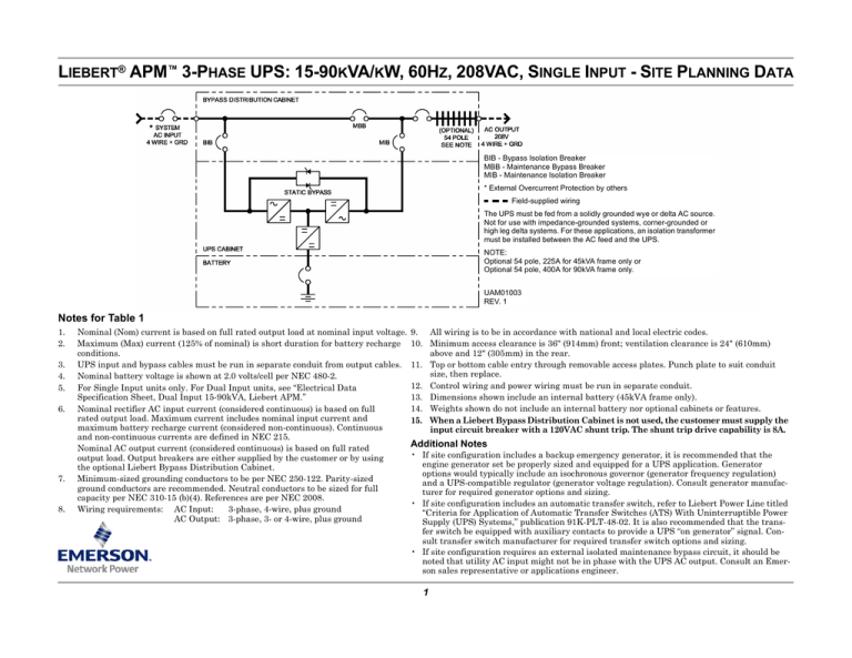
BIB - Bypass Isolation Breaker
MBB - Maintenance Bypass Breaker
MIB - Maintenance Isolation Breaker
* External Overcurrent Protection by others
Field-supplied wiring
The UPS must be fed from a solidly grounded wye or delta AC source.
Not for use with impedance-grounded systems, corner-grounded or
high leg delta systems. For these applications, an isolation transformer
must be installed between the AC feed and the UPS.
NOTE:
Optional 54 pole, 225A for 45kVA frame only or
Optional 54 pole, 400A for 90kVA frame only.
UAM01003
REV. 1
Notes for Table 1
1.
2.
3.
4.
5.
6.
7.
8.
Nominal (Nom) current is based on full rated output load at nominal input voltage.
Maximum (Max) current (125% of nominal) is short duration for battery recharge
conditions.
UPS input and bypass cables must be run in separate conduit from output cables.
Nominal battery voltage is shown at 2.0 volts/cell per NEC 480-2.
For Single Input units only. For Dual Input units, see “Electrical Data
Specification Sheet, Dual Input 15-90kVA, Liebert APM.”
Nominal rectifier AC input current (considered continuous) is based on full
rated output load. Maximum current includes nominal input current and
maximum battery recharge current (considered non-continuous). Continuous
and non-continuous currents are defined in NEC 215.
Nominal AC output current (considered continuous) is based on full rated
output load. Output breakers are either supplied by the customer or by using
the optional Liebert Bypass Distribution Cabinet.
Minimum-sized grounding conductors to be per NEC 250-122. Parity-sized
ground conductors are recommended. Neutral conductors to be sized for full
capacity per NEC 310-15 (b)(4). References are per NEC 2008.
Wiring requirements: AC Input:
3-phase, 4-wire, plus ground
AC Output: 3-phase, 3- or 4-wire, plus ground
9. All wiring is to be in accordance with national and local electric codes.
10. Minimum access clearance is 36" (914mm) front; ventilation clearance is 24" (610mm)
above and 12" (305mm) in the rear.
11. Top or bottom cable entry through removable access plates. Punch plate to suit conduit
size, then replace.
12. Control wiring and power wiring must be run in separate conduit.
13. Dimensions shown include an internal battery (45kVA frame only).
14. Weights shown do not include an internal battery nor optional cabinets or features.
15. When a Liebert Bypass Distribution Cabinet is not used, the customer must supply the
input circuit breaker with a 120VAC shunt trip. The shunt trip drive capability is 8A.
Additional Notes
• If site configuration includes a backup emergency generator, it is recommended that the
engine generator set be properly sized and equipped for a UPS application. Generator
options would typically include an isochronous governor (generator frequency regulation)
and a UPS-compatible regulator (generator voltage regulation). Consult generator manufacturer for required generator options and sizing.
• If site configuration includes an automatic transfer switch, refer to Liebert Power Line titled
“Criteria for Application of Automatic Transfer Switches (ATS) With Uninterruptible Power
Supply (UPS) Systems,” publication 91K-PLT-48-02. It is also recommended that the transfer switch be equipped with auxiliary contacts to provide a UPS “on generator” signal. Consult transfer switch manufacturer for required transfer switch options and sizing.
• If site configuration requires an external isolated maintenance bypass circuit, it should be
noted that utility AC input might not be in phase with the UPS AC output. Consult an Emerson sales representative or applications engineer.
1
Table 1
Site Planning Data - 15-90kVA, 60Hz, 208VAC, Single Input
UPS Rating
Voltage
AC Input
Current, A
Input Output Nom.
Battery
AC Output
Rec. Nom.
Max.
OPD VDC Discharge
Mechanical Data
Input CB
Dimensions
Heat Dis.
Cooling Air (customerOPD WxDxH, in. (mm) 45kVA Frame 90kVA Frame BTU/hr (kWH) CFM (m3/hr) supplied)
Current, A
Unit Weight, lb. (kg)
kVA
kW
15
15
208
208
45
60
80
288
67
42
60
919 (417)
705 (320)
3074 (0.9)
102 (173)
30
30
208
208
90
120
150
288
135
83
125
994 (451)
780 (354)
6147 (1.8)
204 (346)
45
45
208
208
134
180
225
288
202
125
200
306 (519)
60
60
208
208
179
240
300
288
269
167
225
75
75
208
208
224
300
400
288
335
208
300
90
90
208
208
269
360
450
288
404
250
350
1
2,3,5,8,12
6
4
1,3,8,12
1,3,8,12
6
See Notes for Table 1 (p. 1):
Max.
Nom.
31.8x39.5x78.7
(800x1000x2000)
200A
with
120VAC
shunt trip
1069 (485)
855 (388)
9220 (2.7)
NA
930 (422)
12,295 (3.6)
408 (692)
NA
1005 (456)
15,368 (4.5)
510 (865)
NA
1080 (490)
18,442 (5.4)
612 (1038)
400A
with
120VAC
shunt trip
14
14
—
—
15
13
General Specifications
INPUT
OUTPUT
Voltage
Voltage Range without derating
Frequency Range
Current Distortion
Current Walk-In
Power Factor
Surge Protection
ENVIRONMENTAL
Operating Temperature
Non-Operating Temperature
Relative Humidity
Operating Altitude
Acoustical Noise
208/120, 220/127VAC, 50/60Hz, 3-phase, 4-wire plus ground
+15%, -20%
40-70Hz
3% maximum reflected THD at full load
5-35 seconds to full load (adjustable)
0.99 full load, 0.98 half load
Sustains input surges w/o damage, per criteria in IEC 1000-4-5 (with
surge suppressor option ANSI C62.41 (IEEE 587) CAT A3 & B3
Voltage
Voltage Adjustment Range
Voltage
Regulation
Dynamic
Regulation
Transient
Response Time
208/120, 220/127VAC, 50/60Hz, 3-phase, 3- or 4-wire plus ground
UPS: 32° to 104°F (0-40°C); Battery: 68° to 86°F (20-30°C)
-4° to 158°F (-20° to 70°C)
0-95% non-condensing
Up to 3,300 ft. (1,000m) without derating
Less than 57 dBA typical (45kVA), 60 dBA typical (90kVA)
3.3 ft. (1m) from the unit
THD
For linear loads, 1% THD; Less than 4% THD for 100% nonlinear
loads without kVA/kW derating
120° ±1° for balanced load
120° ±1.5° for 100% unbalanced load
±0.1% (single Liebert FlexPower™ assembly)
±0.25% (six Liebert FlexPower assemblies)
Phasing
Balance
Frequency
Regulation
Load Power
Factor Range
Internal Battery
Model
HX100-FR
HX150-FR
Battery
Code
FX
HX
Battery Time (Minutes)
15kVA
30kVA
45kVA
30
12
6
49
21
12
Overload
Added Battery Weight
lb. (kg)
2127 (965)
2605 (1182)
±5%
1% for balanced load
5% for 100% unbalanced load
±5% deviation for 100% load step
±1% for loss or return of AC input
Recover to ±5% of output voltage within 1/2 cycle
0.5 lagging to 0.9 leading without derating
100% load, continuous;
110% load, 60 minutes; 125% load, 10 minutes;
150% load, 60 seconds, with true sinusoidal waveform
STANDARDS
Listed to UL 1778 UPS standards, and CSA certified. Meets current requirements for
safe high performance UPS operation.
© 2010 Liebert Corporation
Technical Support / Service
United States
All rights reserved throughout the world. Specifications subject to change without notice.
1050
Dearborn Drive
800-543-2378
® Liebert is a registered trademark of Liebert Corporation.
All names referred to are trademarks or registered trademarks of their respective owners. powertech@emersonnetworkpower.com P.O. Box 29186
SL-25605_REV2_08-10
Web site: www.liebert.com
2
Columbus, OH 43229


