DATA SHEET
MOUNTING STRAPS AND BRACKETS
DESCRIPTION
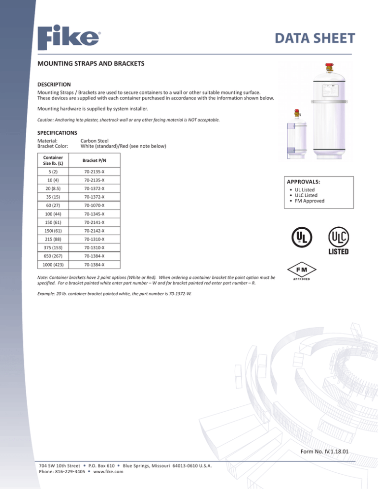
Mounting Straps / Brackets are used to secure containers to a wall or other suitable mounting surface.
These devices are supplied with each container purchased in accordance with the information shown below.
Mounting hardware is supplied by system installer.
Caution: Anchoring into plaster, sheetrock wall or any other facing material is NOT acceptable.
SPECIFICATIONS
Material:
Bracket Color:
Carbon Steel
White (standard)/Red (see note below)
Container
Size lb. (L)
Bracket P/N
5 (2)
70-2135-X
10 (4)
70-2135-X
20 (8.5)
70-1372-X
35 (15)
70-1372-X
60 (27)
70-1070-X
100 (44)
70-1345-X
150 (61)
70-2141-X
150i (61)
70-2142-X
215 (88)
70-1310-X
375 (153)
70-1310-X
650 (267)
70-1384-X
1000 (423)
70-1384-X
APPROVALS:
• UL Listed
• ULC Listed
• FM Approved
Note: Container brackets have 2 paint options (White or Red). When ordering a container bracket the paint option must be
specified. For a bracket painted white enter part number – W and for bracket painted red enter part number – R.
Example: 20 lb. container bracket painted white, the part number is 70-1372-W.
Form No. IV.1.18.01
704 SW 10th Street P.O. Box 610 Blue Springs, Missouri 64013-0610 U.S.A.
Phone: 8162293405 www.fike.com
MOUNTING DETAILS – 5, 10, 20 & 35 LB. (2L, 4L, 8.5L & 15L) CONTAINERS
Container Size
Dimension
5 lb (2L)
IN (mm)
10 lb. (4L)
IN (mm)
20 lb. (8.5L)
IN (mm)
35 lb. (15L)
IN (mm)
A
12.3 (313)
12.3 (313)
16.3 (414)
16.3 (414)
B
4.2 (102)
4.2 (102)
7.0 (178)
7.0 (178)
C
5.7 (145)
5.7 (145)
8.2 (209)
8.2 (209)
D
3.0 (76)
3.0 (76)
5.0 (127)
5.0 (127)
E
2.5 (63.5)
2.5 (63.5)
3.0 (76)
3.0 (76)
F
8.0 (203)
8.0 (203)
9.7 (246)
9.7 (246)
G
1.8 (46)
1.8 (46)
3.6 (91)
3.6 (91)
Mounting Position
Upright (Valve Up)
Upright (Valve Up)
Upright-Horizontal
Upright-Horizontal
Notes:
1.) All dimensions are approximate
2.) When mounting the 20 & 35 lb. (8.5L to 15L) containers in the horizontal position (wall mount or sub-floor mount), the container valve “Pressure Gage”
MUST point up. Failure to comply with this requirement will result in an incomplete discharge.
2 of 6
MOUNTING DETAILS – 60 LB. (27L) CONTAINERS
Dimension
IN (mm)
A
20.00 (508)
B
10.75 (273)
C
13.19 (335)
D
9.00 (229)
E
1.50 (38)
F
0.75 (19)
G
3.50 (89)
H
4.88 (124)
Mounting Position
Upright-Horizontal
Notes:
1.) All dimensions are approximate
2.) When mounting the 60 lb. (27L) container in the horizontal position (wall mount
or sub-floor mount), the container valve “Pressure Gage” MUST point up. Failure to
comply with this requirement will result in an incomplete discharge.
3 of 6
MOUNTING DETAILS – 150 LB. (61L) CONTAINERS
Dimension
IN (mm)
A
17.125 (435)
B
20.00 (508)
C
13.20 (335)
D
11.20 (284)
E
1.00 (25)
F
1.07 (27)
Mounting Position
Upright
Notes:
1.) All dimensions are approximate
2.) The 150 lb. container is equipped with a siphon tube and MUST be mounted in
the upright (valve up) position. Failure to comply with this requirement will result
in an incomplete discharge.
4 of 6
MOUNTING DETAILS – 150i LB. (61L) CONTAINERS
Dimension
IN (mm)
A
19.42 (493)
B
17.75 (451)
C
9.75 (248)
D
1.75 (44)
E
21.62 (549)
F
18.81 (478)
G
14.81 (376)
H
6.81 (173)
I
2.81 (71)
J
21.50 (546)
K
22.27 (566)
Mounting Position
Inverted (Valve Down)
Notes:
1.) All dimensions are approximate
2.) The 150i lb. container is NOT equipped with a siphon tube and MUST be
mounted in the inverted (valve down) position. Failure to comply with this
requirement will result in an incomplete discharge.
5 of 6
MOUNTING DETAILS – 100, 215, 375, 650 & 1000 LB. (44, 88, 153, 267, 423 L) CONTAINERS
P/N
Container Size
70-266
Dimension
Mounting Position
A IN (mm)
B IN (mm)
100 lb (44L)
20.00 (508)
12.25 (311)
Upright (Valve Up)
70-268
215 lb (88L)
11.00 (279)
21.75 (552)
Upright (Valve Up)
70-269
375 lb (153L)
24.00 (610)
21.75 (552)
Upright (Valve Up)
70-270
650 lb (267L)
28.00 (711)
26.00 (661)
Upright (Valve Up)
70-271
1000 lb (423L)
40.00 (1016)
26.00 (661)
Upright (Valve Up)
Notes:
1.) All dimensions are approximate
2.) Mounting Strap can be fastened to the Unistrut Channel with a Unistrut Spring Nut and Bolt.
Copyright © Fike Corporation All Rights Reserved.
Form No. IV.1.18.01, August 2012. Specifications are subject to change without notice.
6 of 6
