Active and reactive power meters and Power factor meters with
advertisement

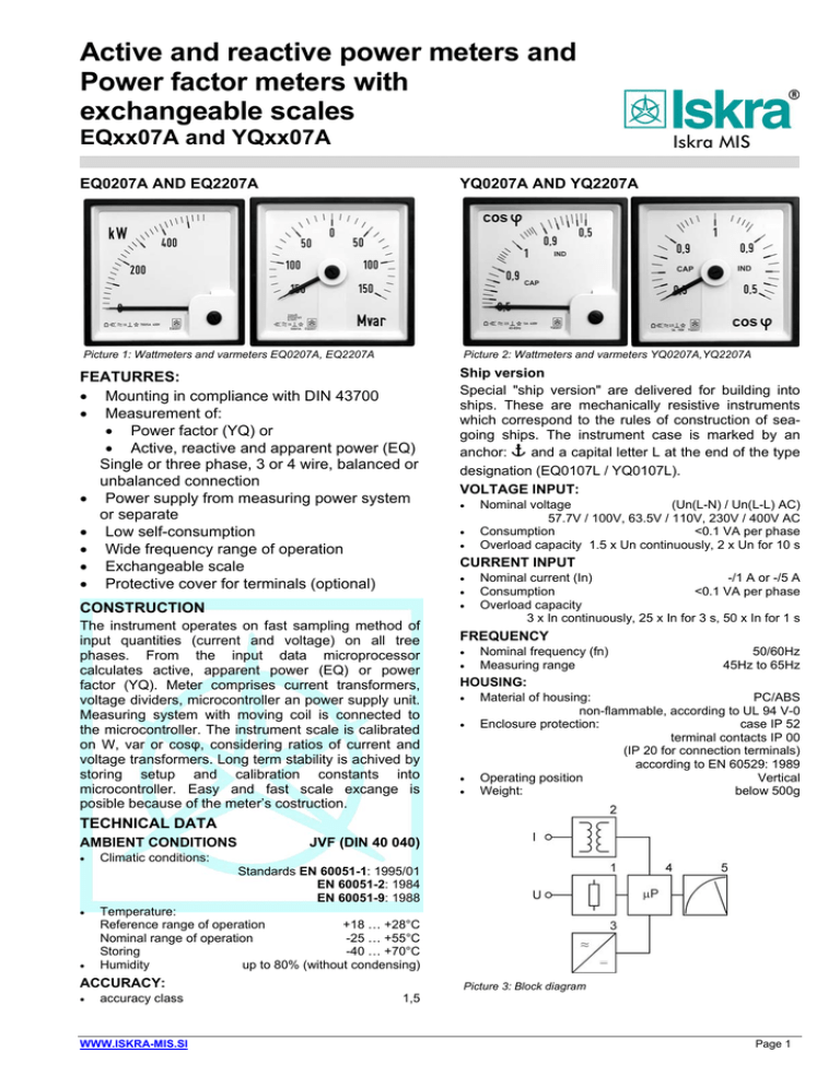
Active and reactive power meters and Power factor meters with exchangeable scales EQxx07A and YQxx07A EQ0207A AND EQ2207A YQ0207A AND YQ2207A Picture 1: Wattmeters and varmeters EQ0207A, EQ2207A Picture 2: Wattmeters and varmeters YQ0207A,YQ2207A FEATURRES: • Mounting in compliance with DIN 43700 • Measurement of: • Power factor (YQ) or • Active, reactive and apparent power (EQ) Single or three phase, 3 or 4 wire, balanced or unbalanced connection • Power supply from measuring power system or separate • Low self-consumption • Wide frequency range of operation • Exchangeable scale • Protective cover for terminals (optional) CONSTRUCTION The instrument operates on fast sampling method of input quantities (current and voltage) on all tree phases. From the input data microprocessor calculates active, apparent power (EQ) or power factor (YQ). Meter comprises current transformers, voltage dividers, microcontroller an power supply unit. Measuring system with moving coil is connected to the microcontroller. The instrument scale is calibrated on W, var or cosφ, considering ratios of current and voltage transformers. Long term stability is achived by storing setup and calibration constants into microcontroller. Easy and fast scale excange is posible because of the meter’s costruction. Ship version Special "ship version" are delivered for building into ships. These are mechanically resistive instruments which correspond to the rules of construction of seagoing ships. The instrument case is marked by an anchor: N and a capital letter L at the end of the type designation (EQ0107L / YQ0107L). VOLTAGE INPUT: • • • Nominal voltage (Un(L-N) / Un(L-L) AC) 57.7V / 100V, 63.5V / 110V, 230V / 400V AC Consumption <0.1 VA per phase Overload capacity 1.5 x Un continuously, 2 x Un for 10 s CURRENT INPUT • • • Nominal current (In) -/1 A or -/5 A Consumption <0.1 VA per phase Overload capacity 3 x In continuously, 25 x In for 3 s, 50 x In for 1 s FREQUENCY • • Nominal frequency (fn) Measuring range 50/60Hz 45Hz to 65Hz HOUSING: • • • • Material of housing: PC/ABS non-flammable, according to UL 94 V-0 Enclosure protection: case IP 52 terminal contacts IP 00 (IP 20 for connection terminals) according to EN 60529: 1989 Operating position Vertical Weight: below 500g TECHNICAL DATA AMBIENT CONDITIONS • JVF (DIN 40 040) Climatic conditions: Standards EN 60051-1: 1995/01 EN 60051-2: 1984 EN 60051-9: 1988 • • Temperature: Reference range of operation +18 … +28°C Nominal range of operation -25 … +55°C Storing -40 … +70°C Humidity up to 80% (without condensing) ACCURACY: • accuracy class WWW.ISKRA-MIS.SI 1,5 Picture 3: Block diagram Page 1 REGULATIONS: • • Protection: Protection class II Aux. supply AC 600 V, installation category III Aux. supply AC / DC 300 V, installation category III Pollution degree 2 Test voltage: 3.7 kV rms according to EN 61010-1: 1990 SCALE Picture 7: Picture 4: Drawing of skale: EQ2207A) Picture 5: Drawing of skale: EQ0207A Picture 6: Drawing of skale: YQ0107A, YQ0207A Drawing of skale: YQ2107A, YQ2207A EXCHANGING OF SCALES Press the cover, on top of the instrument, in the direction of the arrow and extract the scale with a suitable tool. After exchanging the scale, carefully close the opening with the cover. During the replacement procedure the instrument must be disconnected. Picture 8a: Exchanging of scales Picture 8b: Exchanging of scales WWW.ISKRA-MIS.SI Page 2 END SCALE VALUE (EQ): The end scale value is determined as follows: The power to be measured by the instrument can be calculated by using one of the formula below: active reactive Power in single-phase system 3 U I cosϕ 3 U I sinϕ Power in three-phase 3-wire system √3U I cosϕ √3U I sinϕ Power in three-phase 4-wire system 3 U I cosϕ 3 U I sinϕ U in equations the phase voltage in single-phase system, line voltage in three-phase 3-wire system, and phase voltage in three-phase 4-wire systems. According to the calculated value, one of the following standard end scale values and their decade are chosen: 1-1, 2-1, 5-2-2, 5-3-4-5-6-7, 5-8 Accordingly, it has been considered that the scale factor, i.e. the relation between the end scale value and the apparent power (cosϕ or sinϕ is 1) must be within limits of 0,6 ... 1,2. CONNECTION DIAGRAMS Power metres’ and power factor’s voltage inputs can be connected directly to the low-voltage network, or to the high-voltage network via high-voltage transformer. Power metres’ and power factor’s current inputs can be connected to the low-voltage network via current transformer or to the high-voltage network via highvoltage current transformer. Picture 12:Three phase system (four wire balanced - 4b) Picture 9: Single phase system (1b) Picture 13:Three phase system (four wire unbalanced - 4u) Picture 10:Three phase system (three wire balanced - 3b) Picture 14:Connections for full equipped device, position of battery and picture of connectors Picture 11 :Three phase system (three wire unbalanced - 3u) WWW.ISKRA-MIS.SI Page 3 XQ0207A; a; bA; cV; d; (e); f; g DIMENSIONAL DRAWINGS: Description Code Type of instrument: X Instrument specfications Power meter E Factor meter Y Inputs: Type of system Picture 15: Dimensional drawing EQxx07A and YQxx07A (all dimensions are in mm) a Type of connection 1. Protective cover (on special request) EQ0107A EQ2107A EQ0207A EQ2207A YQ0107A YQ2107A YQ0207A YQ2207A Type Bezel height □a (mm) Panel cut-out □b (mm) Bezel height (mm) c 144 138 +1,0 144 144 138 +1 144 96 92 +0,8 96 +0,8 90 90 90 Scales length (mm) 135 135 95 95 End scale value: 54 54 28 54 For EQxxxx 0,5 0,7 3U Three phase system (four wire balanced - 4b) 4B Three phase system (four wire unbalanced - 4u) 4U 1 5A 5 57.74 63.5 VL-N 63.5 230 VL-N 230 any <= calculated max 1) value d xW For YQxxxx 0,5 cap. … 1 … 0,5 ind. 1 0,8 cap. … 1 … 0,3 ind. 2 Type of power meter SPECIFICATION AND ORDERING INFORMATION e Instrument: Auxiliary power supply: For ordering it is necessary to specify: • • • • • • 1A 57.74 VL-N Measuring range phase to neutral 90 Weight 0,9 1,1 approx. (kg) Table 1: Dimensions and weight Three phase system (three wire unbalanced 3u) Nominal input current 96 c □d 3B b Measuring range Protect cover □e (mm) Base (mm) 1B Three phase system (three wire balanced - 3b) Nominal input voltage 96 92 Single phase system (1b) f Type of instrument. Type of system Rated current or current ratio. Rated voltage or voltage ratio. End scale value acc. to technical data. Auxilary power supply. g When ordering "ship version" it is necessary to add a capital letter L at the end of the type designation. Ship version is available only for YQ0207L and EQ0207L. When ordering scales the same data as in case of ordering the instrument must be state. ORDERING EXAMPLE: Instrument for measuring of power factor in single phase system, voltage 230 V, 5 A, measuring range 0.5 cap. ...1... 0.5 ind. YQ0207 – 1b, 230 V, 5 A, 0.5 cap. ...1... 0.5 ind. EQxxxx only Type of power supply Value of power supply voltage (only for AC power supply) Wat, Var or VA meter W/Q/S No external supply - AC auxiliary power supply A 57.74 VL-N E 57.74 100 VL-N E 100 110 VL-N E 110 230 VL-N E 230 400 VL-N E 400 500 VL-N E 500 Table 2: Ordering information 1) See End Scale Value chapter on Page 3. SPECIAL VERSIONS: - Special marking on scale or blank scale - Empty scale - Ship version (YQ0207L and EQ0207L only) - A protective cover against live parts - Zero on any point of the scale Printed in Slovenia • Subject to change without notice • Version 03 / jun.2008 • E P22.430.700


