Plug Gages - Vermont Gage
advertisement
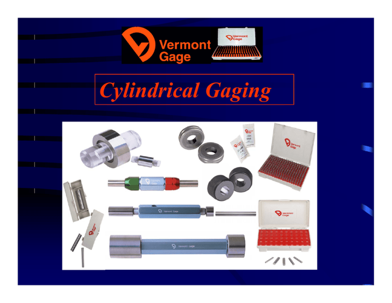
Cylindrical Gaging Diameter Tolerance Chart (ANSI/ASME B89.1.5) Diameter Range Above - Including .010" - .825" .825" - 1.510" 1.510" - 2.510" 2.510" - 4.510" 4.510" - 6.510" 6.510" - 9.010" 9.010" - 12.010" Above - Including .254mm - 20.96mm 20.96mm - 38.35mm 38.35mm - 63.75mm 63.75mm - 114.55mm 114.55mm - 165.35mm 165.35mm - 228.85mm 228.85mm - 305.05mm "XXX" "XX" "X" "Y" "Z" "ZZ" .000070" .000090" .00012" .00015" .00019" .00024" .0003" .0001" .00012" .00016" .0002" .00025" .00032" .0004" .0002" .00024" .00032" .0004" .0005" .00064" .0008" Inch .000010" .000015" .000020" .000025" .000033" .000040" .000050" .000020" .000030" .000040" .000050" .000065" .000080" .0001" .000040" .000060" .000080" .0001" .00013" .00016" .0002" M etric .00025mm .00051mm .00102mm .00178mm .00254mm .00508mm .00038mm .00076mm .00152mm .00229mm .00305mm .00610mm .00051mm .00102mm .00203mm .00305mm .00406mm .00813mm .00064mm .00127mm .00254mm .00381mm .00508mm .01016mm .00084mm .00165mm .00330mm .00483mm .00635mm .01270mm .00102mm .00203mm .00406mm .00610mm .00813mm .01626mm .00127mm .00254mm .00508mm .00762mm .01016mm .02032mm Gage Design Selection Chart INCHES .004- .105- .760.105 .760 1.010 1.0101.510 1.5106.000 REVERSIBLE X X X X X X X X TAPERLOCK TRILOCK X REVERSIBLE PLUG GAGE SETS & REPLACEMENT PINS Range: .006” - 1.0005” & .20mm to 25.49mm Material: Tool Steel (AISI 52100) 60/62 RC Increments: .0005” & .01mm REVERSIBLE PLUG GAGE ASSEMBLIES Range: .004” - 1.010” Materials: Tool Steel 60/62 RC Tolerances: XX, X, Y, Z, & ZZ Chrome Plated 70/72 Rc Carbide 90/92 Ra Assembly Features: Go member: Min Product Hole Size No-Go member: Max Product Hole Size Gage Tolerance: Plus Gage Tolerance: Minus Green cap Red cap * The caps are marked with “ GO “ & “NO-GO” as well as the “Sizes”. The handle is marked with the “Class” & Up to 15 Characters of your choosing. Custom Long Length Reversible Gages Range: .0151” - 1.010” (See Catalog for Size Exceptions!) Lengths: Up to 6” Materials: Tool Steel 60/62 RC Tolerances: XX, X, Y, Z, & ZZ Chrome Plated 70/72 RC Specify: Go, No-Go, or Master Go Class “X” Plain Plug Gages Stocked!! Increment: .0001” Range: .0040” - 1.0000” Tolerance: Plus (.000040”) Material: Tool Steel (Cold Stabilized!) Taperlock Plain Plug Gages Range: .105” - 1.510” Materials: Tool Steel 60/62 RC Tolerances: XX, X, Y, Z, & ZZ Chrome Plated 70 RC Assembly Features: Go member: Min Product Hole Size No-Go member: Max Product Hole Size Gage Tolerance: Plus Gage Tolerance: Minus Long member Short member * The Handle is marked with “ GO “ & “NO-GO” as well as the “Sizes”. The handle is marked with the “Class” & Up to 15 Characters of your choosing. Trilock Cylindrical Plug Gage Range: .760” - 1.510” Materials: Tool Steel 60/62 RC Tolerances: XX, X, Y, Z, & ZZ Chrome Plated 70/72 RC Assembly Features: Go member: Min Product Hole Size No-Go member: Max Product Hole Size Gage Tolerance: Plus Gage Tolerance: Minus Long Member Short Member * The Handle is marked with “ GO “ & “NO-GO” as well as the “Sizes”. The handle is marked with the “Class” & Up to 15 Characters of your choosing. Progressive Plug Gages Range: .105” - 4.510” Materials: Tool Steel (AISI 52100) 60/62 RC Tolerances: XX, X, Y, Z, & ZZ Chrome (Plated Tool Steel) 70/72 RC Assembly Features: Go (Front): Min Product Hole Size No-Go (Back): Max Product Hole Size Gage Tolerance: Plus Gage Tolerance: Minus Front, long portion. Back, short portion * The Handle is marked with “ GO “ & “NO-GO” as well as the “Sizes”. The handle is marked with the “Class” & Up to 15 Characters of your choosing. Other Plain Gage Types •Hex Gages ANSI B18.3 & B107.17M •Master Setting Disc’s Style 1, 2, & 3 Custom Gages •Built to Your Specifications • Developed from Your Part Drawings • Designed to Meet Your Specific Needs • Drawings May Be Supplied, if Required. (All Created Drawings Require Your Approval!) Plug Gages Are: •Used To Inspect Holes or Slots (Pass / Fail) • Used As Masters,(Setting Micrometers, Verniers & Calipers) • Made per ANSI/ASME B89.1.5 Plug Gages Are Not: •Lapping Sticks, Reamers, Or Re-Sizing Tools • De-burring Tools or Die Clean-outs • Used to Measure Actual Size • Hammers or Other Types of “Delicate” Adjustment Tools Remember!!! Never force a Gage into or on a Part Being Check Handle gages as you would any precision tool, misuse or mishandling can result in nicks or other deformities which can destroy the integrity of the gage. Store gages in a secure location, preferably in individual compartments or containers. Gages should be dipped in an oilwax based seal or coated with a rust preventive prior to storing Ship gages packed separately, coated with rust preventive, with sufficient packing material to avoid damage. Any Questions, Contact Us Vermont Gage Division Vermont Precision Tools, Inc. P.O. Box 182 10 Precision Lane Swanton, Vermont 05488 802-868-2701 800-421-0914 802-868-7180 Fax tech@vtgage.com
