installation instructions
advertisement
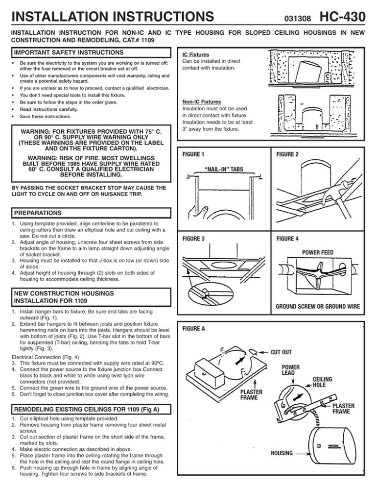
INSTALLATION INSTRUCTIONS 031308 HC-430 INSTALLATION INSTRUCTION FOR NON-IC AND IC TYPE HOUSING FOR SLOPED CEILING HOUSINGS IN NEW CONSTRUCTION AND REMODELING, CAT.# 1109 IMPORTANT SAFETY INSTRUCTIONS • Be sure the electricity to the system you are working on is turned off; either the fuse removed or the circuit breaker set at off. • Use of other manufacturers components will void warranty, listing and create a potential safety hazard. • If you are unclear as to how to proceed, contact a qualified electrician. • You don’t need special tools to install this fixture. • Be sure to follow the steps in the order given. • Read instructions carefully. • Save these instructions. WARNING: FOR FIXTURES PROVIDED WITH 75° C. OR 90° C. SUPPLY WIRE WARNING ONLY (THESE WARNINGS ARE PROVIDED ON THE LABEL AND ON THE FIXTURE CARTON). WARNING: RISK OF FIRE. MOST DWELLINGS BUILT BEFORE 1985 HAVE SUPPLY WIRE RATED 60° C. CONSULT A QUALIFIED ELECTRICIAN BEFORE INSTALLING. IC Fixtures Can be installed in direct contact with insulation. Non-IC Fixtures Insulation must not be used in direct contact with fixture. Insulation needs to be at least 3" away from the fixture. FIGURE 1 FIGURE 2 “NAIL-IN” TABS BY PASSING THE SOCKET BRACKET STOP MAY CAUSE THE LIGHT TO CYCLE ON AND OFF OR NUISANCE TRIP. PREPARATIONS 1. Using template provided, align centerline to be paralleled to ceiling rafters then draw an elliptical hole and cut ceiling with a saw. Do not cut a circle. 2. Adjust angle of housing; unscrew four sheet screws from side brackets on the frame to aim lamp straight down adjusting angle of socket bracket. 3. Housing must be installed so that J-box is on low (or down) side of slope. 4. Adjust height of housing through (2) slots on both sides of housing to accommodate ceiling thickness. FIGURE 3 FIGURE 4 POWER FEED NEW CONSTRUCTION HOUSINGS INSTALLATION FOR 1109 1. Install hanger bars to fixture. Be sure end tabs are facing outward (Fig. 1). 2. Extend bar hangers to fit between joists and position fixture hammering nails on bars into the joists. Hangers should be level with bottom of joists (Fig. 2). Use T-bar slot in the bottom of bars for suspended (T-bar) ceiling, bending the tabs to hold T-bar tightly (Fig. 3). Electrical Connection (Fig. 4) 3. This fixture must be connected with supply wire rated at 90ºC. 4. Connect the power source to the fixture junction box.Connect black to black and white to white using twist type wire connectors (not provided). 5. Connect the green wire to the ground wire of the power source. 6. Don’t forget to close junction box cover after completing the wiring. GROUND SCREW OR GROUND WIRE FIGURE A CUT OUT POWER LEAD CEILING HOLE PLASTER FRAME PLASTER FRAME REMODELING EXISTING CEILINGS FOR 1109 (Fig A) 1. Cut elliptical hole using template provided. 2. Remove housing from plaster frame removing four sheet metal screws. 3. Cut out section of plaster frame on the short side of the frame, marked by slots. 4. Make electric connection as described in above. 5. Place plaster frame into the ceiling rotating the frame through the hole in the ceiling and rest the round flange in ceiling hole. 6. Push housing up through hole in frame by aligning angle of housing. Tighten four screws to side brackets of frame. HOUSING

