BRIDGLAND EPDM RUBBER GASKETS
advertisement
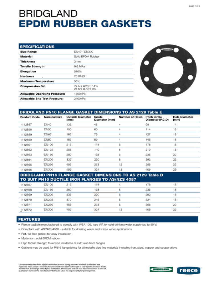
page 1 of 2 BRIDGLAND EPDM RUBBER GASKETS SPECIFICATIONS Size Range DN40 - DN300 Material Solid EPDM Rubber Thickness 3mm Tensile Strength 9.6 MPa Elongation 510% Hardness 70 IRHD Maximum Temperature 50°c Compression Set 72 hrs @23°c 14% 24 hrs @70°c 9% Allowable Operating Pressure: 1600kPa Allowable Site Test Pressure: 2400kPa BRIDGLAND PN16 FLANGE GASKET DIMENSIONS TO AS 2129 Table E Product Code Nominal Size Outside Diameter (mm) Inside Diameter (mm) Number of Holes Pitch Circle Diameter (P.C.D) Hole Diameter (mm) 1112857 DN40 135 48 4 98 14 1112858 DN50 150 60 4 114 18 1112859 DN65 165 76 4 127 18 1112860 DN80 185 89 4 146 18 1112861 DN100 215 114 8 178 18 1112862 DN125 255 140 8 210 18 1112863 DN150 280 168 8 235 22 1112864 DN200 335 220 8 292 22 1112865 DN250 405 273 12 356 22 1112866 DN300 455 324 12 406 26 BRIDGLAND PN16 FLANGE GASKET DIMENSIONS TO AS 2129 Table D TO SUIT PN16 DUCTILE IRON FLANGES TO AS/NZS 4087 1112867 DN100 215 114 4 178 18 1112868 DN150 280 168 8 235 18 1112869 DN200 335 220 8 292 18 1112870 DN225 370 245 8 324 18 1112871 DN250 455 273 8 356 22 1112872 DN300 455 324 12 406 22 FEATURES • Flange gaskets manufactured to comply with WSA 109, type WA for cold drinking water supply (up to 50°c) • Compliant with AS/NZS 4020 - suitable for drinking water and waste water applications • Flat, full face gasket for easy installation • Made from solid EPDM rubber • High tensile strength to reduce incidence of extrusion from flanges • Gaskets may be used for PN16 flange joints for all metallic pipe line materials including iron, steel, copper and copper alloys Disclaimer Products in this specification manual must by regulation be installed by licensed and registered trade people. The manufacturer/distributor reserves the right to vary specifications or delete models from their range without prior notification. Dimensions and set-outs listed are correct at time of publication however the manufacturer/distributor takes no responsibility for printing errors. page 2 of 2 INSTALLATION GUIDE FOR FLANGED JOINTS 1.Make sure that both flange faces are clean. Check bolt threads and nut threads are clean. 2.Apply suitable anti-seize thread lubricant to both nut threads and bolt threads. 3.Check alignment of flanges is parallel and support components to prevent stress on flanged joints throughout assembly. 4.Ensure flange bolts are correct size and length for thickness of flanges. The correct length of bolt should allow 2 complete bolt threads to be visible when the nut is hand tight. 5.Insert 4 bolts into bolt holes 1 to 4 (Fig. 1) and locate the gasket on the bolts carefully to prevent damage to gasket surface. Fit an appropriate size of washer under each bolt head and nut. 6.Align opposite flange carefully and tighten nuts finger tight. 7.Check alignment of flange faces and gasket is straight and even. 8.Insert all remaining bolts and tighten nuts finger-tight. 9.Select the bolt torque required from the Estimated Tightening Torque Values table. Use a torque wrench to assemble bolted connections in the following sequence: a)Tighten nuts to 1/3 of the estimated torque value following the tightening sequence (Fig. 1) b)Tighten nuts to 2/3 of the estimated torque value following the tightening sequence (Fig. 1) c)Tighten nuts to the full estimated torque value following the tightening sequence (Fig. 1) d)Final pass in a clockwise direction, tighten all nuts to the full estimated torque value Fig 1. Flange bolt tighteing sequence Note: 1. If too much torque is applied to fasteners during installation, the gasket can be overstressed causing crushing or extrusion and cause the joint to leak. 2. Refer to WSA 109 Industry Standard for Flange gaskets & O-Rings for further detail ESTIMATED TIGHTENING TORQUE VALUES Nominal Size Bolt Size Lightly oiled grade 4.6 bolts galv. steel bolts & nuts (Nm) Well lubricated grade 4.6 galv. steel bolts (Nm) Well lubricated Grade 316 class 50 stainless steel bolts & nuts* (Nm) DN40 M12 30 20 27 DN50 M16 70 40 65 DN65 M16 70 40 65 DN80 M16 70 40 65 DN100 M16 70 55 65 DN125 M16 70 55 65 DN150 M16 70 55 65 M20 160 105 140 M16 70 55 65 M20 160 105 140 DN225 M16 90 55 65 DN250 M20 160 105 140 DN300 M20 160 85 140 M24 250 130 220 DN200 Note:* Well lubricated bolts & nuts refer to use of molybdenum di-sulphide lubricant or an equivalent anti-galling product WARRANTY You have purchased a quality product from Reece Australia. This product is covered by a 12 month warranty. This warranty covers faults in the product construction, material and assembly. Faulty products will be repaired or exchanged free of charge. Faulty items become our property. This warranty does not include faults caused by • Unsuitable or improper use • Incorrect installation • Normal wear and tear • Inadequate or complete lack of maintenance • Chemical, electrochemical or electrical influences Disclaimer Products in this specification manual must by regulation be installed by licensed and registered trade people. The manufacturer/distributor reserves the right to vary specifications or delete models from their range without prior notification. Dimensions and set-outs listed are correct at time of publication however the manufacturer/distributor takes no responsibility for printing errors. To the maximum extent permitted by law, Reece excludes all warranties other than those set out above. In the event of a warranty claim, we will replace or repair defective products, or pay for the cost of having defective products repaired or replaced, but will not be liable for any injury to any person, damage to any property, any indirect or consequential loss, or in any other respect.
