model ga-21r wide band amplifier
advertisement

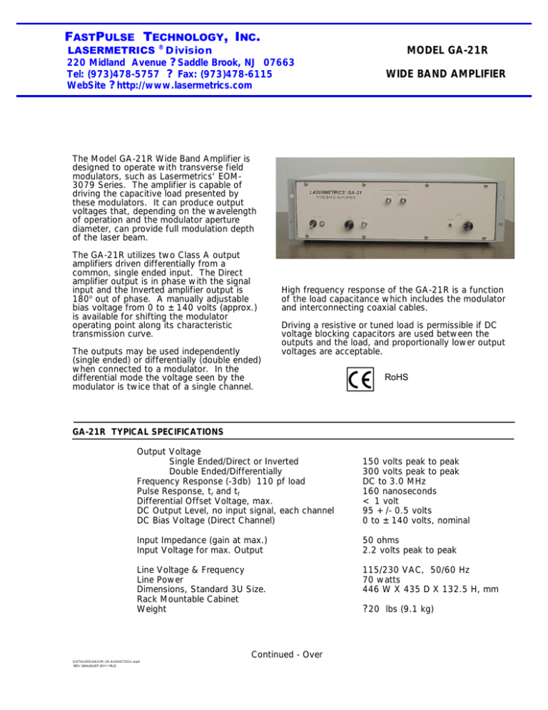
FASTPULSE TECHNOLOGY, INC. LASERMETRICS ® Division 220 Midland Avenue ?Saddle Brook, NJ 07663 Tel: (973)478-5757 ? Fax: (973)478-6115 WebSite ?http://www.lasermetrics.com MODEL GA-21R WIDE BAND AMPLIFIER The Model GA-21R Wide Band Amplifier is designed to operate with transverse field modulators, such as Lasermetrics' EOM3079 Series. The amplifier is capable of driving the capacitive load presented by these modulators. It can produce output voltages that, depending on the wavelength of operation and the modulator aperture diameter, can provide full modulation depth of the laser beam. The GA-21R utilizes two Class A output amplifiers driven differentially from a common, single ended input. The Direct amplifier output is in phase with the signal input and the Inverted amplifier output is 180o out of phase. A manually adjustable bias voltage from 0 to ±140 volts (approx.) is available for shifting the modulator operating point along its characteristic transmission curve. The outputs may be used independently (single ended) or differentially (double ended) when connected to a modulator. In the differential mode the voltage seen by the modulator is twice that of a single channel. High frequency response of the GA-21R is a function of the load capacitance which includes the modulator and interconnecting coaxial cables. Driving a resistive or tuned load is permissible if DC voltage blocking capacitors are used between the outputs and the load, and proportionally lower output voltages are acceptable. RoHS GA-21R TYPICAL SPECIFICATIONS Output Voltage Single Ended/Direct or Inverted Double Ended/Differentially Frequency Response (-3db) 110 pf load Pulse Response, tr and tf Differential Offset Voltage, max. DC Output Level, no input signal, each channel DC Bias Voltage (Direct Channel) 150 volts peak to peak 300 volts peak to peak DC to 3.0 MHz 160 nanoseconds < 1 volt 95 +/- 0.5 volts 0 to ±140 volts, nominal Input Impedance (gain at max.) Input Voltage for max. Output 50 ohms 2.2 volts peak to peak Line Voltage & Frequency Line Power Dimensions, Standard 3U Size. Rack Mountable Cabinet Weight 115/230 VAC, 50/60 Hz 70 watts 446 W X 435 D X 132.5 H, mm \CATALOGS\GA21R--26 AUGUST2011.wpd REV :26AUGUST 2011 / RLG Continued - Over ?20 lbs (9.1 kg) Transverse field modulators are essentially capacitive elements that present a frequency dependent impedance (XC = 1/2? fC) to their driving circuits. Therefore, it is always necessary to minimize capacitance in the modulator and any connecting cables. All Lasermetrics TFMs are designed for minimum internal capacitance and inductance consistent with aperture size and voltage requirements. Since the modulators are sealed, the only variables available to the user are the length and type of interconnecting cable between the modulator and its driving signal source, and the driving signal source itself. Since many coaxial cables exhibit 20 to 30 picofarads/foot, it is important to minimize cable length if frequency response is to be maximized. Most Lasermetrics TFMs are designed with screw terminals for direct attachment of drive cables without the use of connectors. Both terminals are electrically isolated from the modulator outer housing. The outer aluminum housing may be grounded and, depending on the driver, one of the terminals may also be grounded through the connector on the driver front panel and the connecting cable shield. When the electrical driver has only one output connection, such as would be provided by a single coaxial cable the connection is called "single ended" as shown below in A. When the driver has two coaxial cables for the output signal as in B, the connection is called a "double ended", "push-pull" or "balanced output".


