§ Filter Circuits Low Pass Filter : Before carrying out a detailed
advertisement

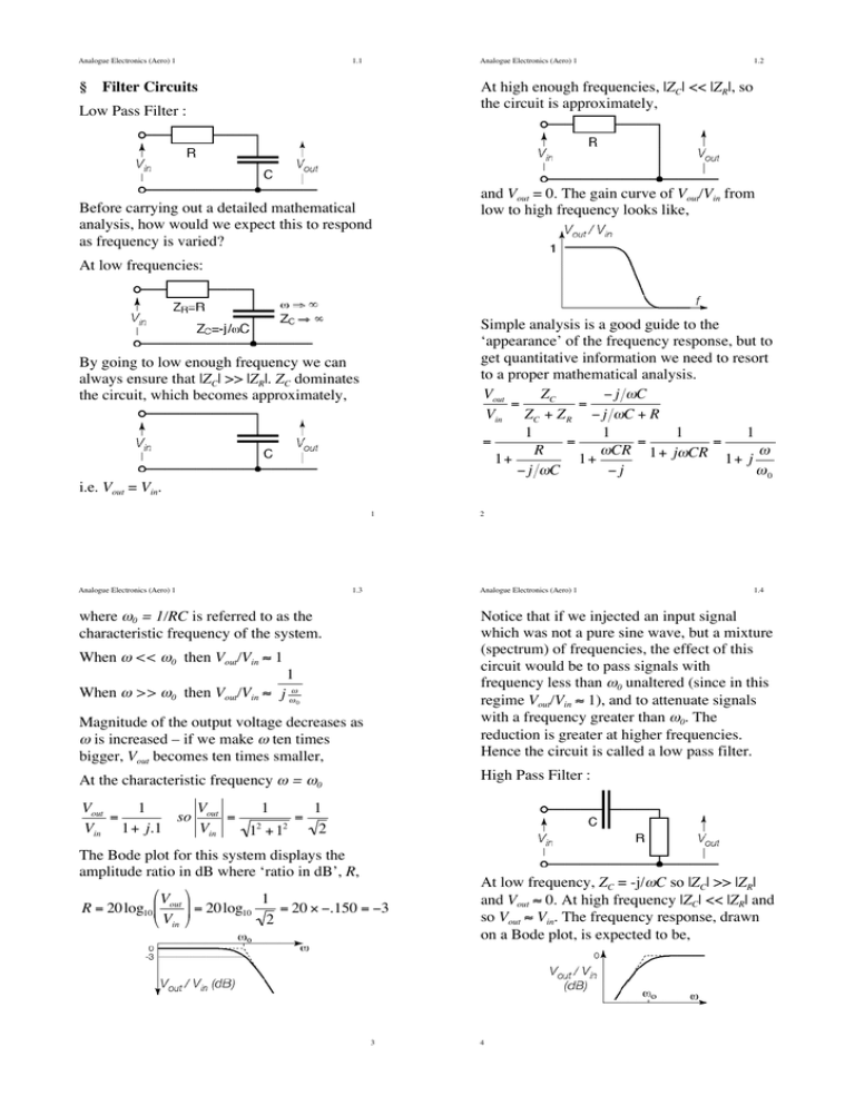
Analogue Electronics (Aero) 1 1.1 Analogue Electronics (Aero) 1 § Filter Circuits 1.2 At high enough frequencies, |ZC| << |ZR|, so the circuit is approximately, Low Pass Filter : and Vout = 0. The gain curve of Vout/Vin from low to high frequency looks like, Before carrying out a detailed mathematical analysis, how would we expect this to respond as frequency is varied? At low frequencies: By going to low enough frequency we can always ensure that |ZC| >> |ZR|. ZC dominates the circuit, which becomes approximately, ! i.e. Vout = Vin. 1 Simple analysis is a good guide to the ‘appearance’ of the frequency response, but to get quantitative information we need to resort to a proper mathematical analysis. Vout ZC " j #C = = Vin ZC + Z R " j #C + R 1 1 1 1 = = = = R #CR 1+ j#CR # 1+ 1+ 1+ j " j #C "j #0 2 ! Analogue Electronics (Aero) 1 1.3 Analogue Electronics (Aero) 1 where !0 = 1/RC is referred to as the characteristic frequency of the system. 1.4 Notice that if we injected an input signal which was not a pure sine wave, but a mixture (spectrum) of frequencies, the effect of this circuit would be to pass signals with frequency less than !0 unaltered (since in this regime Vout/Vin ! 1), and to attenuate signals with a frequency greater than !0. The reduction is greater at higher frequencies. Hence the circuit is called a low pass filter. When ! << !0 then Vout/Vin ! 1 1 When ! >> !0 then Vout/Vin ! j "" 0 Magnitude of the output voltage decreases as ! is increased – if we make ! ten times bigger, Vout becomes ten ! times smaller, At the characteristic frequency ! = !0 High Pass Filter : Vout 1 V 1 1 = so out = 2 2 = Vin 1+ j.1 Vin 2 1 +1 The Bode plot for this system displays the amplitude ratio in dB where ‘ratio in dB’, R, ! "V % 1 R = 20log10 $ out ' = 20log10 = 20 ( ).150 = )3 V 2 # in & At low frequency, ZC = -j/!C so |ZC| >> |ZR| and Vout ! 0. At high frequency |ZC| << |ZR| and so Vout ! Vin. The frequency response, drawn on a Bode plot, is expected to be, ! 3 4 Analogue Electronics (Aero) 1 1.5 Analogue Electronics (Aero) 1 This time the circuit passes high frequency signals and attenuates low frequency signals, acting as a high pass filter. In the high pass and low pass filters we use the fact that the impedance of an RC circuit can be written as R–j/!C or R+jX where the reactive term, X, becomes infinite as ! " ! and tends to zero as ! " 0. However if the reactive part of the circuit arises from a combination of inductors and capacitors we can produce more complex variations of X with frequency and can design circuits to our own specification – in particular we can make X become zero at a specific frequency of interest to us. Vout R 1 = = 1 1 Vin R + 1+ j"C j"CR When ! << !0 then Vout 1 1 = # = j"CR Vin 1+ j"CR 0 + j"CR 1 When ! >> !0 then Vout/Vin ! 1+ j0 ! 1 ! 1.6 Series Resonant Circuits : ! ! The total impedance of the circuit is given by Z = R + j"L # j 5 6 ! Analogue Electronics (Aero) 1 1.7 Given particular values of L and C we can make the reactive term, X, vanish if we choose the frequency ! to be a particular !O such that, "O L # 1 1 1 = 0 $ "O L = $ "O2 = "O C "O C LC fO = ! 1 1 = 2"# 2" LC ! At this resonant frequency, the impedance of the circuit is Z = R because X = 0. Since the magnitude of Z is ! Z = R 2 + ("L # "1C ) at any other frequency the magnitude of Z will be greater than R. This means that the magnitude of any current flows are at a maximum at the resonant frequency. 2 7 $ 1 1 ' = R + j&"L # ) = R + jX % "C "C (


