Overload Relays
advertisement

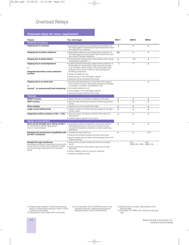
04_Sec.qxd 07/28/03 11:19 AM Page 4/2 Overload Relays Overload relays for every requirement Overload relay Feature Your advantages 3RU11 3RB10 3RB12 Protection functions Tripping due to overload • guarantees optimal current-dependent protection of the loads against impermissibly high temperature rises as a result of an overload. x x x Tripping due to phase unbalance • guarantees optimal current-dependent protection of the loads against impermissibly high temperature rises as a result of phase unbalance. (x) x x Tripping due to phase failure • minimises the heating of the three-phase motor during single-phase operation 1). x x 2) x • permits optimal temperature-dependent protection of loads against impermissibly high temperature rises, e. g. for stator-critical motors, reduced coolant flow, pollution of the motor surface or long starting and breaking procedures • saves an additional unit • saves space in the switchgear cabinet • reduces wiring complexity and costs 3 3 x Tripping due to overtemperature by integrated thermistor motor protection function ) • permits optimal protection of the load in the case of minor short-circuits or earth faults caused by damage by to insulation, humidity, condensation, etc. internal 4) or external earth fault monitoring • eliminates additional unit • saves space in the switchgear cabinet • reduces wiring complexity and costs Tripping due to an earth fault ) x Features RESET function • allows manual or automatic resetting of the relay. x x x TEST function • permits easy checking of correct functioning and the wiring. x x x Status display • signals the current operational state. x x x Large current setting knob • makes it easier to set the relay accurately to the right current value. x x x Integrated auxiliary contacts (1 NO + 1 NC) • allow the load to be disconnected in the case of a disturbance • enable tripped signals to be output. x x x Short-circuit strength up to 100 kA at 690 V • guarantees optimum protection of the load and the (in combination with the appropriate operating personnel in the event of short-circuits fuse or circuit-breaker) caused by insulation breakdown or faulty switching operations. x x x Electrical and mechanical compatibility with • simplifies project planning the 3RT1 contactors • reduces the project engineering work and costs • permits space-saving direct mounting apart from individual mounting. x x x 5) Design of load feeders Straight-through transformer • reduces the contact resistances (only one contact (the leads are directly routed short-circuit-proof point) to the main terminals of the contactor through • saves connection costs (quick, easy and no tools the feed-through openings of the overload required) relay) • saves material costs (no need for busbars) • reduces installation costs. 1) Single-phase operation: Abnormal operating state of a three-phase induction motor in which a phase is interrupted. 2) Tripping from warm state within 3 seconds. 4/2 3) In combination with the 3RN thermistor motor protection devices, additional temperaturebased protection can be implemented. only only 3RB10 56-. FW0 3RB12 46-. . . . 4) Special device variants: See selection and ordering data. 5) Exception: For 3RB12 46, individual mounting only. Siemens Energy & Automation, Inc. Industrial Controls Catalog 04_Sec.qxd 07/28/03 11:19 AM Page 4/3 Feature Overload Relays 1 Overload relays for every requirement 2 Your advantages 3RU11 3RB10 3RB12 Further characteristics Temperature compensation • allows implementation of the relay at high temperatures without derating • prevents premature tripping • permits compact design of the switchgear cabinet without the need for clearance between the devices and/or load feeders • simplifies project planning • allows space to be saved in the switchgear cabinet. x x x High long-term stability • guarantees reliable protection of loads even after years of operation under harsh conditions. x x x Wide adjustment ranges • reduce the number of variants • minimise the project engineering work and costs • provide savings in inventories in terms of work, costs and capital tie-up. x x Release classes > CLASS 10 • permit solutions for heavy starting and extremely heavy starting. x x Minimal power losses • reduce the energy consumption (the energy consumption is up to 95 % lower than for thermal overload relays) and therefore the energy costs • minimise the temperature rise for the contactor and switchgear cabinet – which may obviate the need for a cabinet cooling system • allow space to be saved by direct mounting on the contactor and in the case of high motor currents (i. e. heat isolation is not necessary). x x • saves project engineering and connection of an additional control circuit. • reduces the number of variants Variable setting of the release classes The release class required can be set in accor- • minimises the project engineering work and costs dance with the prevailing start-up conditions by • permits savings in inventories in terms of work, costs means of a six-position rotary switch (CLASS 5, and capital tie-up. 10, 15, 20, 25 or 30) Internal power supply 1 ) x • allows an analog output signal to be output to control instruments, PLCs or to bus systems • saves an additional transducer and signal converter • saves space in the switchgear cabinet • reduces wiring complexity and costs x Overload warning • indicates impending tripping of the relay due to an overload, phase unbalance or phase failure directly on the device • enables impending tripping of the relay to be signalled via an external indicator lamp connected to the corresponding auxiliary contacts2) • permits early implementation of countermeasures in the case of long-term current-dependent loading of the consumer above the limit current • saves an additional relay • saves space in the switchgear cabinet • reduces wiring complexity and costs x Siemens Energy & Automation, Inc. Industrial Controls Catalog and therefore do not require an additional control circuit. 4 x Analog output 2) 1) The SIRIUS 3RU11 thermal overload relays operate according to the bimetal-strip principle 3 2) Special device variants: See selection and ordering data 4/3


