APPLICATION NOTE
Output Voltage Ripple in Step-Down and Step-Up Switching Regulators
Introduction
Output voltage ripple is always an important performance parameter with DC-DC converters. For inductor-based switching regulators, several key factors can affect this important parameter, including switching frequency, duty cycle, and
output capacitor value. Step-down and step-up switching regulators have different circuit topologies, so some factors
that affect the output voltage ripple for step-down DC-DC converters will not affect output voltage ripple for step-up
DC-DC converters.
This application note analyzes factors affecting output voltage ripple based on the derived output voltage ripple equations for step-down and step-up DC-DC converter topologies in CCM. This document can help provide insight in understanding output voltage ripple.
Step-Down Converter Output Ripple
Step-Down IC
IN
SW
Control
Circuit
+
IL
Q1
PMOS
VS
L
Q2
NMOS
C
R
VO
FB
-
GND
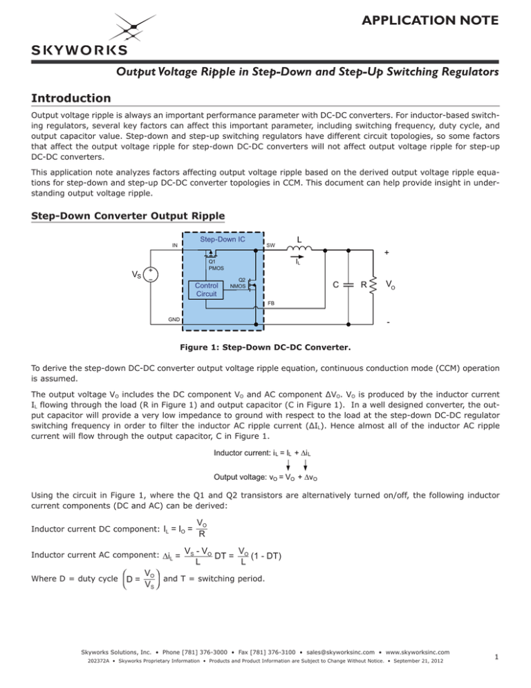
Figure 1: Step-Down DC-DC Converter.
To derive the step-down DC-DC converter output voltage ripple equation, continuous conduction mode (CCM) operation
is assumed.
The output voltage VO includes the DC component VO and AC component ∆VO. VO is produced by the inductor current
IL flowing through the load (R in Figure 1) and output capacitor (C in Figure 1). In a well designed converter, the output capacitor will provide a very low impedance to ground with respect to the load at the step-down DC-DC regulator
switching frequency in order to filter the inductor AC ripple current (ΔIL). Hence almost all of the inductor AC ripple
current will flow through the output capacitor, C in Figure 1.
Inductor current:: i L = IL + ∆i L
Output voltage: vO = VO + ∆vO
Using the circuit in Figure 1, where the Q1 and Q2 transistors are alternatively turned on/off, the following inductor
current components (DC and AC) can be derived:
Inductor current DC component:IL = IO =
VO
R
Inductor current AC component: ∆iL = VS - VO DT = VO (1 - DT)
V
Where D = duty cycle D = O
VS
L
L
and T = switching period.
Skyworks Solutions, Inc. • Phone [781] 376-3000 • Fax [781] 376-3100 • sales@skyworksinc.com • www.skyworksinc.com
202372A • Skyworks Proprietary Information • Products and Product Information are Subject to Change Without Notice. • September 21, 2012
1
APPLICATION NOTE
Output Voltage Ripple in Step-Down and Step-Up Switching Regulators
The output capacitor charging and discharging current is equal to the inductor AC ripple current. Figure 2 illustrates the
typical output capacitor voltage ripple waveform resulting from the inductor AC ripple current flowing through the output capacitor. Using the “blue section”, or area under the waveform, of the output capacitor current (iC) waveform in
Figure 2, the output voltage ripple equation can be derived:
∆vf =
∆iC
VO
=
(1 - D)
8 · f · C 8 · f2 · L · C
VSW
VS
Q1 close
Q2 open
0
Q1 open
Q2 close
DT
t
T
iL
IO
∆i L
0
DT
2
t
DT (1+D)T T
2
iC
∆iC=∆iL
0
DT
2
DT
(1+D)T
2
t
T
vO
VO
∆vO
0
DT
2
DT (1+D)T T
t
2
Figure 2: Typical Waveforms of a Step-Down Converter.
From the output voltage ripple equation, switching frequency (f), duty cycle (D), inductor value (L) and output capacitor value (C) can all affect output voltage ripple. The data curves in Figure 3 illustrate the effect of these parameters
on output voltage ripple.
2
Skyworks Solutions, Inc. • Phone [781] 376-3000 • Fax [781] 376-3100 • sales@skyworksinc.com • www.skyworksinc.com
202372A • Skyworks Proprietary Information • Products and Product Information are Subject to Change Without Notice. • September 21, 2012
APPLICATION NOTE
Output Voltage Ripple in Step-Down and Step-Up Switching Regulators
Step-Down Output Ripple vs. Frequency and C
Step-Down Output Ripple vs. Frequency and L
(C = 10µF; D = 0.50)
50
Output Voltage Ripple (mV)
Output Voltage Ripple (mV)
(L = 2.2µH; D = 0.50)
C = 4.7µF
C = 10µF
C = 22µF
40
30
20
10
0
0.5
1
1.5
2
2.5
3
Frequency (MHz)
50
L = 1.4µH
L = 2.2µH
L = 4.7µH
L = 6.8µH
40
30
20
10
0
0.5
1
1.5
2
2.5
Frequency (MHz)
(a)
3
(b)
Buck Output Ripple vs. Frequency and Duty
Output Voltage Ripple (mV)
(L = 2.2µH, C = 10µF)
50
D = 0.72
D = 0.50
D = 0.33
40
30
20
10
0
0.5
1
1.5
2
2.5
3
Frequency (MHz)
(c)
Figure 3: The Effect of Four Parameters [f, D, L, C] on Step-Down Converter Output Voltage Ripple.
From Figure 3, the following is observed:
• Switching frequencies between 1MHz ~ 2MHz result in 10mV or less output voltage ripple for output capacitor values
of 4.7µF ~ 22µF and inductor values of 1.4μH ~ 6.8µH without high switching losses.
• As the duty cycle is increased, output voltage ripple is decreased. In other words, duty cycle is inversely proportional to output voltage ripple.
• As the inductor value is increased, output voltage ripple is decreased. In other words, inductor value is inversely
proportional to output voltage ripple.
• The output current has no effect on the output voltage ripple of a step-down DC-DC converter.
Skyworks Solutions, Inc. • Phone [781] 376-3000 • Fax [781] 376-3100 • sales@skyworksinc.com • www.skyworksinc.com
202372A • Skyworks Proprietary Information • Products and Product Information are Subject to Change Without Notice. • September 21, 2012
3
APPLICATION NOTE
Output Voltage Ripple in Step-Down and Step-Up Switching Regulators
Step-Up Converter Output Ripple
L
Step-Up IC
IN
SW
IL
D1
+
ID1
Control
Circuit
VS
Q1
NMOS
C
R
VO
FB
-
GND
Figure 4: Step-Up DC-DC Converter.
As with the step-down DC-DC converter, the step-up DC-DC converter output voltage ripple can be derived from the
output capacitor charging and discharging current (iC) for CCM operation. Figure 5 illustrates the output voltage ripple
waveform resulting from the capacitor current (iC).
Time:
Capacitor current:
DT
vo
ic = R
Using small ripple approximation
Capacitor current:
(1-D)T
vo
ic = iL R
vo ≈ Vo
iL ≈ IL, vo ≈ V o
Vo
ic = - R
ic = IL -
Integrate the capacitor current
Output voltage ripple:
Where D = duty cycle (D = 1 -
4
VS
)
VO
∆vo =
D • T • Vo
R•C
=
Vo
R
IL • R - Vo
• (1-D)T
R•C
and T = switching period.
Skyworks Solutions, Inc. • Phone [781] 376-3000 • Fax [781] 376-3100 • sales@skyworksinc.com • www.skyworksinc.com
202372A • Skyworks Proprietary Information • Products and Product Information are Subject to Change Without Notice. • September 21, 2012
APPLICATION NOTE
Output Voltage Ripple in Step-Down and Step-Up Switching Regulators
VSW
VO - VD1
Q1 close
Q1 open
0
DT
t
T
iC
IL -
VO
R
0
DT
VO
R
t
T
vO
∆v O
VO
0
DT
2
DT (1+D)T T
t
2
Figure 5: Typical Waveforms of a Step-Up DC-DC Converter.
Using the
vO =
1
∫ i dt equation,
C c
the step-up DC-DC converter output voltage ripple is derived:
∆vO =
Where D = duty cycle (D = 1 -
VS
)
VO
D · VO · T D · IO
=
R·C
C·f
and f = switching frequency = 1/T.
The data curves in Figure 6 illustrate the effect of duty cycle (D), output current (IO), output capacitor value (C), and
switching frequency (f) on step-up DC-DC converter output voltage ripple (∆vO). From those data curves, the following
can be observed:
• As the duty cycle is increased, output voltage ripple is increased. In other words, the duty cycle is proportional to
output voltage ripple.
• As the output capacitor value is decreased, output voltage ripple is increased. In other words, output capacitor value
is inversely proportional to output voltage ripple.
• As the output current is increased, output voltage ripple is increased. In other words, output current is proportional
to output voltage ripple.
• The inductor value has no effect on the output voltage ripple of a step-up DC-DC converter.
Skyworks Solutions, Inc. • Phone [781] 376-3000 • Fax [781] 376-3100 • sales@skyworksinc.com • www.skyworksinc.com
202372A • Skyworks Proprietary Information • Products and Product Information are Subject to Change Without Notice. • September 21, 2012
5
APPLICATION NOTE
Output Voltage Ripple in Step-Down and Step-Up Switching Regulators
Step-Up Output Ripple vs. Frequency and C
Step-Up Output Ripple vs. Frequency and D
(L = 2.2µH; D = 0.50)
200
D = 0.76
D = 0.52
D = 0.28
150
100
50
0
0.5
Output Voltage Ripple (mV)
Output Voltage Ripple (mV)
(C = 10µF; IO = 1A)
1
1.5
2
2.5
3
Frequency (MHz)
250
C = 4.7µF
C = 10µF
C = 22µF
200
150
100
50
0
0.5
1
1.5
2
2.5
Frequency (MHz)
(a)
Output Voltage Ripple (mV)
(D = 0.50; C = 10µF)
200
IO = 0.1A
IO = 0.5A
IO = 1.0A
150
100
50
0
1
1.5
2
2.5
3
Frequency (MHz)
(c)
Figure 6: The Effect of Four Parameters [f, D, IO, C] on Step-Up Converter Output Voltage Ripple.
6
(b)
Step-Up Output Ripple vs. Frequency and IO
0.5
3
Skyworks Solutions, Inc. • Phone [781] 376-3000 • Fax [781] 376-3100 • sales@skyworksinc.com • www.skyworksinc.com
202372A • Skyworks Proprietary Information • Products and Product Information are Subject to Change Without Notice. • September 21, 2012
APPLICATION NOTE
Output Voltage Ripple in Step-Down and Step-Up Switching Regulators
Conclusion
For step-up and step-down inductor based DC-DC converters, factors affecting output voltage ripple overlap for both
converter topologies. The common factors for both DC-DC converter topologies are switching frequency, output
capacitor value, and duty cycle. For the step-up DC-DC converter, inductor value is not a factor in influencing the
output voltage ripple, while for the step-down DC-DC converter it is. This is also true for output current; Table 1 provides a brief comparison of the two different topologies regarding factors/parameters which influence output voltage
ripple.
Factors Affecting Output Voltage Ripple
Type
Output Voltage Ripple Formula
D · IO
C·f
D=1-
VO
(1 - D)
8·f ·L·C
D=
∆vO =
Step-Up
Step-Down
∆vO =
Duty
2
VS
VO
VO
VS
Switch Frequency
L
√
√
√
C
D
IO
√
√
√
√
√
Table 1: Factors and Parameters that Affect Output Voltage Ripple
in Step-Down and Step-Up DC-DC Converter Topologies.
Copyright © 2012 Skyworks Solutions, Inc. All Rights Reserved.
Information in this document is provided in connection with Skyworks Solutions, Inc. (“Skyworks”) products or services. These materials, including the information contained herein, are provided by Skyworks as a
service to its customers and may be used for informational purposes only by the customer. Skyworks assumes no responsibility for errors or omissions in these materials or the information contained herein. Skyworks may change its documentation, products, services, specifications or product descriptions at any time, without notice. Skyworks makes no commitment to update the materials or information and shall have no
responsibility whatsoever for conflicts, incompatibilities, or other difficulties arising from any future changes.
No license, whether express, implied, by estoppel or otherwise, is granted to any intellectual property rights by this document. Skyworks assumes no liability for any materials, products or information provided hereunder, including the sale, distribution, reproduction or use of Skyworks products, information or materials, except as may be provided in Skyworks Terms and Conditions of Sale.
THE MATERIALS, PRODUCTS AND INFORMATION ARE PROVIDED “AS IS” WITHOUT WARRANTY OF ANY KIND, WHETHER EXPRESS, IMPLIED, STATUTORY, OR OTHERWISE, INCLUDING FITNESS FOR A PARTICULAR
PURPOSE OR USE, MERCHANTABILITY, PERFORMANCE, QUALITY OR NON-INFRINGEMENT OF ANY INTELLECTUAL PROPERTY RIGHT; ALL SUCH WARRANTIES ARE HEREBY EXPRESSLY DISCLAIMED. SKYWORKS DOES
NOT WARRANT THE ACCURACY OR COMPLETENESS OF THE INFORMATION, TEXT, GRAPHICS OR OTHER ITEMS CONTAINED WITHIN THESE MATERIALS. SKYWORKS SHALL NOT BE LIABLE FOR ANY DAMAGES, INCLUDING BUT NOT LIMITED TO ANY SPECIAL, INDIRECT, INCIDENTAL, STATUTORY, OR CONSEQUENTIAL DAMAGES, INCLUDING WITHOUT LIMITATION, LOST REVENUES OR LOST PROFITS THAT MAY RESULT FROM
THE USE OF THE MATERIALS OR INFORMATION, WHETHER OR NOT THE RECIPIENT OF MATERIALS HAS BEEN ADVISED OF THE POSSIBILITY OF SUCH DAMAGE.
Skyworks products are not intended for use in medical, lifesaving or life-sustaining applications, or other equipment in which the failure of the Skyworks products could lead to personal injury, death, physical or environmental damage. Skyworks customers using or selling Skyworks products for use in such applications do so at their own risk and agree to fully indemnify Skyworks for any damages resulting from such improper
use or sale.
Customers are responsible for their products and applications using Skyworks products, which may deviate from published specifications as a result of design defects, errors, or operation of products outside of published parameters or design specifications. Customers should include design and operating safeguards to minimize these and other risks. Skyworks assumes no liability for applications assistance, customer product
design, or damage to any equipment resulting from the use of Skyworks products outside of stated published specifications or parameters.
Skyworks, the Skyworks symbol, and “Breakthrough Simplicity” are trademarks or registered trademarks of Skyworks Solutions, Inc., in the United States and other countries. Third-party brands and names are for
identification purposes only, and are the property of their respective owners. Additional information, including relevant terms and conditions, posted at www.skyworksinc.com, are incorporated by reference.
Skyworks Solutions, Inc. • Phone [781] 376-3000 • Fax [781] 376-3100 • sales@skyworksinc.com • www.skyworksinc.com
202372A • Skyworks Proprietary Information • Products and Product Information are Subject to Change Without Notice. • September 21, 2012
7


