SBVA012 - Texas Instruments
advertisement

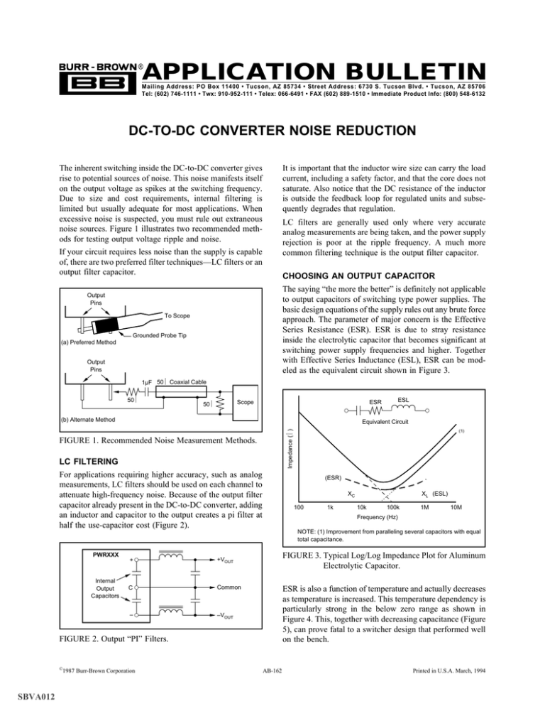
APPLICATION BULLETIN ® Mailing Address: PO Box 11400 • Tucson, AZ 85734 • Street Address: 6730 S. Tucson Blvd. • Tucson, AZ 85706 Tel: (602) 746-1111 • Twx: 910-952-111 • Telex: 066-6491 • FAX (602) 889-1510 • Immediate Product Info: (800) 548-6132 DC-TO-DC CONVERTER NOISE REDUCTION The inherent switching inside the DC-to-DC converter gives rise to potential sources of noise. This noise manifests itself on the output voltage as spikes at the switching frequency. Due to size and cost requirements, internal filtering is limited but usually adequate for most applications. When excessive noise is suspected, you must rule out extraneous noise sources. Figure 1 illustrates two recommended methods for testing output voltage ripple and noise. If your circuit requires less noise than the supply is capable of, there are two preferred filter techniques—LC filters or an output filter capacitor. It is important that the inductor wire size can carry the load current, including a safety factor, and that the core does not saturate. Also notice that the DC resistance of the inductor is outside the feedback loop for regulated units and subsequently degrades that regulation. LC filters are generally used only where very accurate analog measurements are being taken, and the power supply rejection is poor at the ripple frequency. A much more common filtering technique is the output filter capacitor. CHOOSING AN OUTPUT CAPACITOR The saying “the more the better” is definitely not applicable to output capacitors of switching type power supplies. The basic design equations of the supply rules out any brute force approach. The parameter of major concern is the Effective Series Resistance (ESR). ESR is due to stray resistance inside the electrolytic capacitor that becomes significant at switching power supply frequencies and higher. Together with Effective Series Inductance (ESL), ESR can be modeled as the equivalent circuit shown in Figure 3. Output Pins To Scope Grounded Probe Tip (a) Preferred Method Output Pins 1µF 50Ω Coaxial Cable 50Ω (b) Alternate Method Impedance (Ω) Equivalent Circuit LC FILTERING For applications requiring higher accuracy, such as analog measurements, LC filters should be used on each channel to attenuate high-frequency noise. Because of the output filter capacitor already present in the DC-to-DC converter, adding an inductor and capacitor to the output creates a pi filter at half the use-capacitor cost (Figure 2). Internal Output Capacitors + +VOUT C Common – –VOUT (ESR) XC 100 SBVA012 1987 Burr-Brown Corporation 1k XL (ESL) 10k 100k 1M 10M Frequency (Hz) NOTE: (1) Improvement from paralleling several capacitors with equal total capacitance. FIGURE 3. Typical Log/Log Impedance Plot for Aluminum Electrolytic Capacitor. ESR is also a function of temperature and actually decreases as temperature is increased. This temperature dependency is particularly strong in the below zero range as shown in Figure 4. This, together with decreasing capacitance (Figure 5), can prove fatal to a switcher design that performed well on the bench. FIGURE 2. Output “PI” Filters. © (1) AB-162 Printed in U.S.A. March, 1994 Application Bulletin Number 162 FIGURE 1. Recommended Noise Measurement Methods. PWRXXX ESL ESR Scope 50Ω capacitors in parallel that add to the needed capacitance and reduce the ESR by the parallel resistance relation (see note in Figure 3). The second capacitor may be 1/10 or 1/100 the capacitance of the first, since it will provide bypassing for higher frequencies. 20 ESR Ratio 15 There are two basic families of electrolytic capacitors from which to choose: aluminum and tantalum. Aluminum types are available in many quality grades and fabrication techniques. Tantalum types come in foil, solid, and wet-slug subtypes. At first, this may present a bewildering array of choices, but these can quickly be reduced by your particular need. Cheap aluminum electrolytics of questionable quality are often used but all too frequently this leads to actual noise generation, with poor reliability, and, in general, criticisms of high frequency switching type supplies. Good quality aluminum electrolytics probably provide the best compromise, if one must be made, between cost and performance. These are “computer grade” and other types made especially for switchers. Some have specialized construction that produce very low ESR and ESL rather than low cost. The outstanding feature of all tantalum types is their high capacitance to volume efficiency. This is particularly seen in the wet-slug tantalum, an undisputed winner in the capacitance versus volume contest. Solid tantalums appeal where there is a great emphasis on longevity, both shelf life and operating life. The foil-type tantalum is a very good capacitor for switchers but is not cost competitive with aluminum types. Where switching frequencies are very high (1MHz and greater) and current demands are low, nonelectrolytic capacitors will probably replace the previously discussed electrolytics, providing bypassing at high frequencies where the ESL of electrolytics becomes too high. 10 5 1 0 –40 –30 –20 –10 0 10 20 30 40 Temperature (°C) FIGURE 4. ESR Ratio Relative to Room Temperature. Capacitance Ratio 1 0.75 0.50 0.25 0 –40 –30 –20 –10 0 10 20 30 40 Temperature (°C) In addition to considering the capacitance, ESR, ESL, and appropriate voltage derating for the application, most capacitors have a maximum rms ripple current (or max rms ripple voltage) rating which should not be exceeded. Ripple current can be estimated by iRMS = ip–p/3.5 (or VRMS = VP-P/3.0). These ratings are too often ignored, but the stress produced by exceeded ripple will adversely effect the lifespan of the output filter capacitor. The effect of ripple current flowing in the output capacitor is the dissipation of heat in the capacitor’s ESR. Heat kills electrolytics in two ways— electrolytic depletion and electrolytic evaporation. The rate at which the electrolyte is lost depends on the electrolyte itself and the capacitor’s internal structure. But whatever that rate, tests by aluminum capacitor makers indicate it nearly doubles for each 10°C rise in temperature. Thus, each 10°C rise nearly cuts the usable life of an aluminum capacitor in half. The best approach to counter this problem is to use capacitors designed and rated for higher temperatures. FIGURE 5. Capacitive Ratio Relative to Room Temperature. The ESR becomes, in effect, a voltage divider with the internal output resistance of the supply. Therefore, the lower the ESR, the better suited the capacitor is for filtering the output of a switching type power supply. As the load increases, the capacitors’ ripple current increases, causing a larger drop across the ESR, and consequently, a larger output ripple voltage (seen as noise). A commonly used method for estimating ESR is by means of the equation: ESR = DF x 0.01/2πfC Where DF is given in %, f is given in hertz, and C is given in farads. Dissipation factor (DF) is a function of frequency and is useless if given at less than 1kHz. (If given at lower frequencies, it is more indicative of equivalent parallel resistance). If given a 1kHz or greater, the above equation applies. Typical values are 8% to 24% at 1kHz for solid tantalums, and 0.1% to 3% at 1kHz for ceramics, and 8% at 120Hz for aluminum electrolytics. Most tantalum and aluminum electrolytic capacitor manufacturers do not specify the ESR, probably because it is not worth bragging about. One way of reducing ESR in design is to put two or more Whatever capacitor is selected, its effective use depends greatly upon wiring techniques. For example, inductance can become dominant if good wiring practices are not followed and a low ESL requirement can be reduced through very careful wiring. Place the capacitor as close as possible to the load rather than the power supply. The reason for this 2 is the presence of inductance in the wire or PCB trace and the existing output capacitor inside the supply. A small pi filter is formed furthering the reduction of noise. Capacitor lead length including circuit wiring on both sides of the capacitor should be minimized. Short, wide straps are the best and these can be paralleled for further reduction in selfinductance. PWR623B It’s true that good capacitors have played a big role in making switching type power supplies a technological and commercial success, but this success has inspired the capacitor makers to devise even better suited types. Because of this impetus and the versatility of the switching power supply, it is difficult to say that one type of capacitor is inherently better than another. Most capacitor manufacturers are willing and able to provide advice that would help you in your decision. 1 2π + –VIN – + +VOUT C Common – –VOUT 100µH Inductors: Siemens B78108-S1104 1µF Capacitors: Sprague 150D105 X9020A2 FIGURE 6. Filter Circuit for DC/DC Converter. EXAMPLE: FILTERING THE PWR623 The circuit in Figure 6, developed for and in use by a customer, is representative of the necessary considerations in filtering high frequency switching power supplies. In the components, the calculated break (or 3dB) frequency should be significantly less than the ripple frequency. A first order analysis will contain several sources of error. These errors include the effects of loading, internal resistance, ESR of the inductor, and most importantly the ESR and ESL of the capacitor. In a first order analysis of an LC filter, the break frequency can be found by setting the inductive reactance equal to the capacitive reactance and solving for frequency. (f). 1 2πf L = 2πf C f= +VIN Output Voltage/Input Voltage (dB) 0 15.92kHz –10 –40dB/dec –20 –30 –40 –50 100 1k 10k 100k 1M Frequency (Hz) 1 LC FIGURE 7. Linear First Order Approximation of Filter Circuit. For our example, the inductor was 100µH and the capacitor was 1µF. This yielded a break frequency of 15.92kHz (Figure 7), which is an order of magnitude below the ripple frequency of the PWR6XX series (approximately 160kHz). The PWR623 product data sheet shows a typical ripple of 30mVp–p. Upon bench testing the circuit (Figure 6) at rated load (±67mA), the noise was reduced to below the capabilities of the general test equipment being used. The information provided herein is believed to be reliable; however, BURR-BROWN assumes no responsibility for inaccuracies or omissions. BURR-BROWN assumes no responsibility for the use of this information, and all use of such information shall be entirely at the user's own risk. Prices and specifications are subject to change without notice. No patent rights or licenses to any of the circuits described herein are implied or granted to any third party. BURR-BROWN does not authorize or warrant any BURR-BROWN product for use in life support devices and/or systems. 3 IMPORTANT NOTICE Texas Instruments and its subsidiaries (TI) reserve the right to make changes to their products or to discontinue any product or service without notice, and advise customers to obtain the latest version of relevant information to verify, before placing orders, that information being relied on is current and complete. All products are sold subject to the terms and conditions of sale supplied at the time of order acknowledgment, including those pertaining to warranty, patent infringement, and limitation of liability. TI warrants performance of its semiconductor products to the specifications applicable at the time of sale in accordance with TI’s standard warranty. Testing and other quality control techniques are utilized to the extent TI deems necessary to support this warranty. Specific testing of all parameters of each device is not necessarily performed, except those mandated by government requirements. Customers are responsible for their applications using TI components. In order to minimize risks associated with the customer’s applications, adequate design and operating safeguards must be provided by the customer to minimize inherent or procedural hazards. TI assumes no liability for applications assistance or customer product design. TI does not warrant or represent that any license, either express or implied, is granted under any patent right, copyright, mask work right, or other intellectual property right of TI covering or relating to any combination, machine, or process in which such semiconductor products or services might be or are used. TI’s publication of information regarding any third party’s products or services does not constitute TI’s approval, warranty or endorsement thereof. Copyright 2000, Texas Instruments Incorporated

