Installation Guide
HPX-P200/P250-PC-xx Hydraport Power Outlet Modules
Overview
HPX-P250-PC-AU
HPX-P200/P250-PC-xx Hydraport AC Power Modules are designed to be used
exclusively in the AMX HPX-600, HPX-900 or HPX-1200 Hydraport® Chassis.
There are four models available to accommodate various regional power outlet
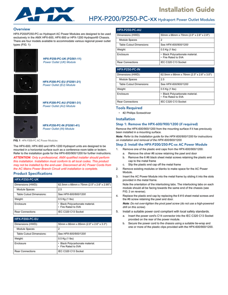
types (FIG. 1):
Dimensions (HWD):
HPX-P250-PC-UK (FG561-11)
Power Outlet (UK) Module
Module Spaces
Table Cutout Dimensions:
50mm x 66mm x 70mm (2.0" x 2.6" x 2.8")
2
See HPX-600/900/1200
Weight:
0.5 Kg (1 lbs)
Enclosure
• Black Polycarbonate material.
• Fire Rated to 5VA
Rear Connections
IEC C320 C13 Socket
HPX-P250-PC-IN
Dimensions (HWD):
Module Spaces
HPX-P200-PC-EU (FG561-21)
Power Outlet (EU) Module
HPX-P200-PC-AU (FG561-31)
Power Outlet (AU) Module
Table Cutout Dimensions:
62.5mm x 66mm x 76mm (2.5" x 2.6" x 3.0")
2.5
See HPX-600/900/1200
Weight:
0.5 Kg (1 lbs)
Enclosure
• Black Polycarbonate material.
• Fire Rated to 5VA
Rear Connections
IEC C320 C13 Socket
Tools Required
•
#2 Phillips Screwdriver
Installation
HPX-P250-PC-IN (FG561-41)
Power Outlet (IN) Module
Step 1: Remove the HPX-600/900/1200 (if required)
Remove the HPX-600/900/1200 from the mounting surface if it has previously
been installed in a mounting surface.
Note: Refer to the Installation guide for the HPX-600/900/1200 for instructions
on installation and removal of the HPX-600/900/1200.
FIG. 1 HPX-P200-PC AC Power Modules
The HPX-600, HPX-900 and HPX-1200 Hydraport units are designed to be
mounted in a horizontal surface such as a conference room table or lectern.
Refer to the installation guide for the HPX-600/900/1200 for further instructions.
ATTENTION: Only a professional, AMX-qualified installer should perform
this installation. Installation must conform to all local codes. This product
may not be installed by the end-user. Disconnect all AC Power Cords from
the AC Mains Power Branch Circuit until installation is complete.
Product Specifications
Step 2: Install the HPX-P200/250-PC-xx AC Power Module
1.
c.
Module Spaces
Table Cutout Dimensions:
Remove existing modules or blanks to make space for the AC Power
Module.
3.
Insert the AC Power Module into the metal frame by sliding it into the slots
provided in the metal frame.
Note the orientation of the interlocking tabs. The interlocking tabs on each
module should all be facing towards the same end of the chassis (see
FIG. 2 on reverse).
62.5mm x 66mm x 75mm (2.5" x 2.6" x 2.95")
2.5
See HPX-600/900/1200
Remove the silver #6 screw retaining the pawl and door
Remove the 6 #6 black sheet metal screws retaining the plastic end
cap to the metal frame
Slip the plastic end cap off the metal frame
2.
HPX-P250-PC-UK
Dimensions (HWD):
Remove one of the plastic end caps from the HPX-600/900/1200:
a.
b.
Weight:
0.5 Kg (1 lbs)
4.
Replace the plastic end cap by replacing the 6 # 6 sheet metal screws and
the #6 screw retaining the pawl and door.
Enclosure
• Black Polycarbonate material.
• Fire Rated to 5VA
Note: Do not over-tighten the pivot pawl screw (do not use a high-powered
drill on this screw).
Rear Connections
IEC C320 C13 Socket
5.
Install a suitable power cord compliant with local safety standards.
a.
HPX-P200-PC-EU
Dimensions (HWD):
Module Spaces
Table Cutout Dimensions:
50mm x 66mm x 85mm (2.0" x 2.6" x 3.3")
2
See HPX-600/900/1200
Weight:
0.5 Kg (1 lbs)
Enclosure
• Black Polycarbonate material.
• Fire Rated to 5VA
Rear Connections
IEC C320 C13 Socket
b.
Insert the power cord's C14 connector into the IEC C320 C13 Socket
provided on the rear of the power module.
Secure the power cord to the chassis using a suitable tie-wrap and
one or more of the plastic clips provided with the HPX-600/900/1200.
Note: Refer to the Installation guide for the HPX-600/900/1200 as required.
Step 4: Plug the HPX-P200/250-PC-xx into the Branch Circuit
Connect an appropriate power cord in to the power module.
Plug the power outlet plug into the AC Mains Power Branch Circuit.
HPX Base Assembly
Interlocking tab
Cables
End Cap
Mounting Surface
FIG. 2 Installing the HPX-P200/P250-PC-xx Module
Step 3: Replace the HPX-600/900/1200
Reinstall the HPX-600/900/1200 by reversing Step 1.
For full warranty information, refer to the AMX Instruction Manual(s) associated with your Product(s).
1/12
©2012 AMX. All rights reserved. AMX and the AMX logo are registered trademarks of AMX.
AMX reserves the right to alter specifications without notice at any time.
3000 RESEARCH DRIVE, RICHARDSON, TX 75082 • 800.222.0193 • fax 469.624.7153 • technical support 800.932.6993 • www.amx.com
93-0561-02
REV: A


