3 3
3
F p F p
Laws of gyroscopes / 3-axis gyroscope
TEP
Principle
The momentum of inertia of the gyroscope is investigated by measuring the angular
acceleration caused by torques of different known values. In this experiment, two of the
axes of the gyroscope are fixed.
The relationship between the precession frequency and the gyro-frequency of the
gyroscope with 3 free axes is examined for torques of different values applied to the axis of
rotation. If the axis of rotation of the force-free gyroscope is slightly displaced, a nutation
is induced. The nutation frequency will be investigated as a function of gyro-frequency.
Related topics
Momentum of inertia, torque, angular momentum, precession, nutation.
Tasks
1. Determination of the momentum of inertia of the gyroscope by measurement of the
angular acceleration.
2. Determination of the momentum of inertia by measurement of the gyro-frequency and
precession frequency. Investigation of the relationship between precession and gyrofrequency and its dependence on torque.
3. Investigation of the relationship between nutation frequency and gyro-frequency.
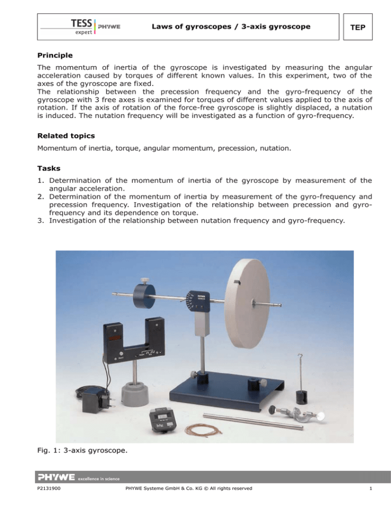
Fig. 1: 3-axis gyroscope.
P2131900
PHYWE Systeme GmbH & Co. KG © All rights reserved
1
TEP
Laws of gyroscopes / 3-axis gyroscope
Equipment
1
1
1
1
1
1
4
1
1
Gyroscope with 3 axes
Light barrier with counter
Power supply 5 V DC/2.4 A
Additional gyro-disc w. counter-weight
Stopwatch, digital, 1/100 sec.
Barrel base -PASSSlotted weight, 10 g, black
Slotted weight, 50 g, black
Holder for slotted weights
02555-00
11207-30
11076-99
02556-00
03071-01
02006-55
02205-01
02206-01
02204-00
Set-up and procedure
The experimental set-up is shown in Fig 1:
1. To start with, the polar momentum of inertia Ip of the gyroscope disk must be
determined. For this, the gyroscope is fixed with its axis directed horizontally and
positioned on the experimenting table in such a way that the thread drum projects over
the edge of the table (Fig. 2). The thread is wound around the drum and the
accelerating mass m (m = 60 g; plate with 5 slotted weights) is fastened to the free end
of the thread. Several experiments are carried out for different drop heights h of the
accelerating mass, from which the corresponding average falling time tF from the
moment the gyroscope disk is released until the mass touches the floor is determined.
The diagram of tF2 versus h is plotted and the moment of inertia of the gyroscope disk is
determined from the slope of the straight line (Fig. 3).
2. The gyroscope, on which no forces act, and which can move freely around its 3 axes, is
wound up and the duration tR of one revolution (rotation frequency) is determined by
means of the forked light barrier, with the axis of the gyroscope lying horizontally.
Immediately after this, a mass m* = 30 g is hung at a distance r* = 27 cm into the groove at
the longer end of the gyroscope axis. The duration of half a precession rotation tp/2
must now be determined with a manual stopwatch (this value must be multiplied by two
for the evaluation). The mass is then removed, so the gyroscope axis can regain
immobility, and tR can be determined again. The inverse of the average value from both
measurements of tR is entered into a diagram above precession time tP. In the same way,
the other measurement points are recorded for decreasing number of gyroscope
rotations. The slope of the resulting straight line allows to calculate the momentum of
inertia of the gyroscope disk (Fig. 6).
3. If a slight lateral blow is given against the axis of the rotating gyroscope on which no
forces are acting, the gyroscope starts describing a nutation movement. The duration of
one nutation tN is determined with the manual stopwatch and this is plotted against the
duration of one revolution tR, which is again determined by means of the forked light
barrier (Fig. 7).
2
PHYWE Systeme GmbH & Co. KG © All rights reserved
P2131900
3 3
3
F p F p
Laws of gyroscopes / 3-axis gyroscope
TEP
Theory and evaluation
1. Determination of the momentum of inertia of the gyroscope disk
If the gyroscope disk is set to rotate by means of a falling mass m (Fig. 2), the following
relation is valid for the angular acceleration:
d ωR
M
= α =
dt
IP
(1)
(ωR = angular velocity; α = angular acceleration; Ip =polar momentum of inertia;
M =F · r = torque)
According to the law of action and reaction, the force which causes the torque is given by
the following relation:
F = m⋅( g −a )
(2)
(g = terrestrial gravitational acceleration; a = trajectory acceleration)
The following relations are true for the trajectory acceleration a and the angular
acceleration α:
a =
P2131900
2h
a
; α =
2
r
tF
PHYWE Systeme GmbH & Co. KG © All rights reserved
(3)
3
TEP
Laws of gyroscopes / 3-axis gyroscope
(h = dropping height of the accelerating mass, tF = falling time; r = radius of the thread
drum). Introducing (2) and (3) into (1), one obtains:
(4)
2
tF =
2
2 I p+ 2 mr
mgr 2
⋅h
From the slope of the straight line tF2= f(h) from Fig. 3, one obtains the following value for
the momentum of inertia of the gyroscope disk:
Ip= (8,83 ± 0,15)·10-3 kg m²
In general, the following is valid for the momentum of inertia of a disk:
IP =
1
2
4
M ⋅R = π ⋅R ⋅d ⋅ ρ
2
2
(5)
Taking the corresponding values for the radius R and the thickness d of the circular disk,
and the specific weight of plastic ρ =0,9 g/cm3, one obtains from (4):
Ip= 8,91·10-3 kg m²
4
PHYWE Systeme GmbH & Co. KG © All rights reserved
P2131900
3 3
3
F p F p
Laws of gyroscopes / 3-axis gyroscope
TEP
2. Determination of the precession frequency
Let the symmetrical gyroscope G in Fig. 4, which is suspended so as to be able to rotate
around the 3 main axes, be in equilibrium in horizontal position with counterweight C. If
the gyroscope is set to rotate around the x-axis, with an angular velocity ω the following is
valid for the angular momentum L, which is constant in space and in time:
L = I P ⋅ω R
(6)
Adding a supplementary mass m* at the distance r* from the support point induces a
supplementary torque M*, which is equal to the variation in time of the angular momentum
and parallel to it.
M * = m*⋅ g⋅r * =
dL
dt
(7)
Due to the influence of the supplementary torque (which acts perpendicularly in this
particular case), after a lapse of time dt, the angular momentum L will rotate by an angle
dφ from its initial position (Fig. 5).
d L = L⋅d ϕ
(8)
The gyroscope does not topple under the influence of the supplementary torque, but reacts
perpendicularly to the force generated by this torque. The gyroscope, which now is
submitted to gravitation, describes a so-called precession movement.
The angular velocity φP of the precession fulfills the relation:
ωP =
P2131900
dϕ
1⋅d L
1⋅d L
m *⋅ g⋅r *
=
=
=
I P ⋅ω R
dt
L⋅dt
I P⋅ω R⋅d t
PHYWE Systeme GmbH & Co. KG © All rights reserved
(9)
5
TEP
Laws of gyroscopes / 3-axis gyroscope
Taking ωP = 2π / tP and ωR = 2π / tR one obtains:
*
*
1
m ⋅g ⋅r 1
=
⋅t
2
tR
IP P
4π
(10)
According to (10), Fig. 6 shows the linear relation between the inverse of the duration of a
revolution tR of the gyroscope disk and the duration of a precession revolution tP for two
different masses m* The slopes of the straight lines allow calculating the values of the
momentum of inertia, for which one obtains:
Ip= (8,89 ± 0,15) kg m2 for m* = 0,03 kg
6
and
Ip= (9,29 ± 0,17) kg m2 for m* = 0,06 kg
PHYWE Systeme GmbH & Co. KG © All rights reserved
P2131900
3 3
3
F p F p
Laws of gyroscopes / 3-axis gyroscope
TEP
The double value of the torque (double value of m*) causes the doubling of the precession
frequency.
If m* is hung into the forward groove of the gyroscope axis, or if the direction of rotation of
the disk is inverted, the direction of rotation of the precession is also inverted.
If the supplementary disk identical to the gyroscope disk is used too, and both are caused
to rotate in opposite directions, no precession will occur when a torque is applied.
3. Determination of the nutation frequency
Fig. 7 represents the relation
ω N = k ω R ; tR = k tN
(11)
between the nutation frequency ωN and rotation frequency ωR The constant k depends on the different
moments of inertia relative to the principal axes of rotation.
P2131900
PHYWE Systeme GmbH & Co. KG © All rights reserved
7

