B. Short Circuit Test
advertisement
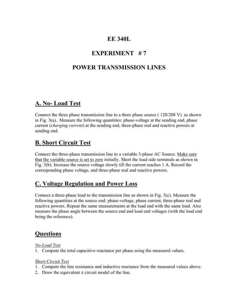
EE 340L EXPERIMENT # 7 POWER TRANSMISSION LINES A. No- Load Test Connect the three phase transmission line to a three phase source ( 120/208 V) as shown in Fig. 3(a).. Measure the following quantities: phase-voltage at the sending end, phase current (charging current) at the sending end, three-phase real and reactive powers at sending end. B. Short Circuit Test Connect the three-phase transmission line to a variable 3-phase AC Source. Make sure that the variable source is set to zero initially. Short the load side terminals as shown in Fig. 3(b). Increase the source voltage slowly till the current reaches 1 A. Record the corresponding phase voltage, and three-phase real and reactive powers. C. Voltage Regulation and Power Loss Connect a three-phase load to the transmission line as shown in Fig. 3(c). Measure the following quantities at the source end: phase-voltage, phase current, three-phase real and reactive powers. Repeat the same measurements at the load end with the same load. Also measure the phase angle between the source end and load end voltages (with the load end being the reference). Questions No-Load Test 1. Compute the total capacitive reactance per phase using the measured values. Short-Circuit Test 1. Compute the line resistance and inductive reactance from the measured values above. 2. Draw the equivalent π circuit model of the line. Line Voltage Regulation and Power Loss 1. Compute the voltage regulation of the transmission line under the specific load tested. Also calculate the line losses in terms of both real and reactive powers. 2. Use PSpice Circuit model and compare the simulated quantities (Vr, Is, Ir, Ps, Pr …) to the measured quanties. a a’ b b’ c c’ Fig. 3(a) a a’ b b’ c c’ Fig. 3(b) a a’ b b’ c c’ R=150Ω L=0.4H Fig. 3(c) Recorded Data No load test: V(phase) = 115 V Is = 0.08 A Ps = 0 W Qs = 30 VAR Short Circuit Test: Vs(phase) = 15 V Is = 1 A Ps = 18 W Qs = 41 VAR Ckt Under Load Vs(phase) = 115 V Is = 1.40 A Ps = 425 W Qs = 235 VAR Vr(phase) = 96 V Ir = 1.48 A Pr = 400 W Qr = 400 VAR Phase angle (of Vs with respect to Vr) = 7 degrees
