Port Elizabeth, New Jersey, USA
advertisement

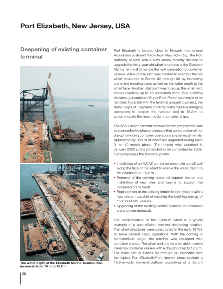
Port Elizabeth, New Jersey, USA Deepening of existing container terminal Port Elizabeth is located close to Newark International Airport and a stone’s throw from New York City. The Port Authority of New York & New Jersey recently decided to upgrade the thirty-year-old wharf structures at the Elizabeth Marine Terminal to handle the next generation of container vessels. A five-phase plan was created to overhaul the old wharf structures at Berths 82 through 98 by increasing crane and mooring loads as well as the water depth at the wharf face. Another vital point was to equip the wharf with cranes reaching up to 18 containers wide, thus enabling the latest generation of Super Post-Panamax vessels to be handled. In parallel with the terminal upgrading project, the Army Corps of Engineers currently plans massive dredging operations to deepen the harbour bed to 15.2 m to accommodate the most modern container ships. The $650-million terminal redevelopment programme was sequenced in five phases to ensure that construction will not disrupt on-going container operations at existing terminals. Approximately 350 m of wharf are upgraded during each 9- to 12-month phase. The project was launched in January 2002 and is scheduled to be completed by 2009. It encompasses the following points: • Installation of an HZ/AZ combined sheet pile cut-off wall along the face of the wharf to enable the water depth to be increased to -15.2 m • Removal of the existing crane rail support beams and installation of new piles and beams to support the increased crane loads • Replacement of the existing timber fender system with a new system capable of resisting the berthing energy of 150,000-DWT vessels • Upgrading of the existing electric systems for increased crane power demands. The water depth of the Elizabeth Marine Terminal was increased from 10 m to 15.2 m 20 The modernisation of the 1,830-m wharf is a typical example of a cost-efficient terminal-deepening solution. The wharf structures were constructed in the early 1970’s to serve general cargo operations. With the coming of containerised cargo, the terminal was equipped with container cranes. The wharf and cranes were able to serve Panamax container vessels with a draught of up to 12.2 m. The main part of Berths 82 through 98 coincides with the typical Port Elizabeth/Port Newark cross-section: a 15.2-m-wide low-level-platform consisting of a 30-cm +2.00 +1.50 –0.00 Existing Sheet Piling HZ 575 A, B & C - 12 L=24.50 m -10.00 AZ 18 L=7.50 m Existing Mudline -15.20 Future Dredge Depth -22.50 A cut-off HZ/AZ combined sheet pile wall was driven in front of the existing terminal HZ 575 king piles / AZ 18 intermediary sheet pile combined wall concrete deck slab supported by timber piles. Tie rods attached to a deadman system provide the lateral stability of the wharf structure. The crane rail beams are supported by timber and steel piles. The first step in the design of wharf improvement, inspection of the existing wharf, showed that all the elements of the existing structure were in good condition. The design office appointed for the project, Han Padron Associates, determined that combining the new construction with the existing wharf structures was the optimum and most economical improvement alternative. Construction time was considerably reduced by choosing to improve the existing structure rather than completely demolishing and replacing the wharf. Provision was also made in the design for new supporting piles for the crane rails. The advantage of the cut-off sheet pile wall chosen is the ability to retain the existing mudline elevation beneath the wharf while permitting the area in front of the toe wall to be dredged to the desired depth. Since requirements for earthquake design were not included in the building codes at the time the existing wharf was built, a seismic analysis had to be performed to ensure that the upgraded structure complies with current codes. After evaluating the wharf’s stability under static and seismic loading conditions, the project team chose a coated HZ/AZ combined-wall system along the face of the wharf as the most cost-efficient solution. Several of the wharf improvement elements were governed by the seismic loading, including the size of the HZ king piles and anchor bolts. The assessments of the structural upgrades depend on geotechnical conditions. The general geological profile of the site consists of hydraulic fill above soft and loose silt and clays overlying dense sand and gravel and underlain by sandstone and shale bedrock. The principal concern regarding overall global stability after the planned dredging works was a slip-circle type of failure. Slope-stability analyses of the riprap slope determined that the tips of the HZ king piles needed to be driven into the dense sand and gravel layers in order to achieve sufficient stability. Driving the king piles through these denser layers also resulted in the optimum wall design with maximum passive pressure on the wall. 21 King-pile driving with two-layer template A special beam transmitted the vibration energy to the underwater AZ-piles Failure Surface Original Mudline New Mudline The installation equipment was not submerged Owner: APMT NORTH AMERICA Designer: Han Padron Associates, New York Sheet pile system: HZ 575 A, B & C –12 / AZ18 Length of HZ king piles: 23.0 m / 24.5 m Length of AZ sheet piles: 7.5 m Steel grade: Grade 50 (yield strength: 355 N/mm2) HZ connectors: S 430 GP Total quantity of sheet piles: 2,440 metric tons 22 To transform the existing terminal of the 1970’s into a state-of-the-art container terminal accommodating 6,600-TEU vessels the following cut-off combined sheet pile wall was installed at the wharf face: HZ 575 king piles with AZ 18 intermediary sheet piles. The sheet pile wall permitted dredging of the harbour bed to -15.2 m while maintaining the stability of the slope beneath the relieving platform. Soil and static analyses showed that it was necessary to anchor the top of the king piles. The HZ piles were anchored into the concrete fascia wall to reduce bending moment, deformations and embedment depth of the king piles in comparison to a cantilever solution. Driving works were simplified considerably due to the fact that the heads of the king piles remained above Slip-circle type of failure was of concern with respect to the stability of the new wharf the water line. A two-level driving template equipped with supporting consoles was set on the existing quay wall. A quayside crane lifted the king piles brought in by barge and lowered them into the driving guide. The template was equipped with neoprene shields to protect the coating system of the sheet piles. A vibratory hammer first drove the HZ piles until refusal; an impact hammer then drove them to the design depth. Since the design called for the king piles to be attached to the existing quay wall, the head of the piles remained 2 m above the waterline. Underwater driving was thus not necessary for the installation of the HZ piles. Furthermore, the king piles were used as support for the combined fender and panel system that provides the necessary standoff between ship and toe wall. The king piles also acted as a guiding frame for the installation of the intermediary sheet piles. The contractor did not want to submerge the vibratory hammer and thus opted for a special beam that transmitted the vibration energy from the installation equipment to the AZ piles throughout the driving process to design depth. The underwater AZ sheet piles prevent soil erosion due to the turbulence caused by ships’ screws. The heads of the HZ king piles remained above the water line, which facilited their installation… Projects similar to the terminal deepening described above have been carried out in numerous ports all over the world. Many marine container terminals in operation today were originally built to accommodate Panamax size vessels (draught up to 12 m). In order to remain competitive, ports are now forced to accommodate Post-Panamax ships. Quay walls constructed in the 1970s have to be modernised to receive these large vessels. A very quick and cost-efficient solution for upgrading wharves is to install stabilising steel sheet pile walls in front of the existing wharf to permit deepening operations. HZ/AZ combined sheet pile systems were also used for the following projects in Port of Elizabeth: • P&O Container Terminal, Port of Newark, delivery: 2001 4,630 t HZ 775 B - 12 / AZ 18 L HZ = 25 – 30 m, L AZ = 13.5 – 16 m • APMT NORTH AMERICA Marine Terminal, Phase 1, Port of Elizabeth, delivery: 2002 1,350 t HZ 575 B&C -12 / AZ 18 L HZ = 24.5 m, L AZ = 7.5 m • APMT NORTH AMERICA Marine Terminal, Phase 2, Port of Elizabeth, delivery: 2003 1,090 t HZ 575 A&B -12 / AZ 18 L HZ = 23 m, L AZ = 7.5 m • Maher Terminals, Modernisation of berth 75 - 78, Port of Elizabeth, delivery: 2003 2,260 t HZ 775 C -12 / AZ 18 …and provided an ideal support for the fenders of the terminal Neoprene shields attached to the template protected the coating system during installation 23


