RF-RS-T
Date of Issue: 05/09/2014
Issue Number: 5.2
Page 1 of 5
RF-RS-T
Battery Powered Temperature Sensors
Features:
Up to 5 years battery life
Encrypted data transmission
Configurable parameters
Benefits:
Self-healing tree topology
Lower installation costs
Easy to install and commission
Technical Overview
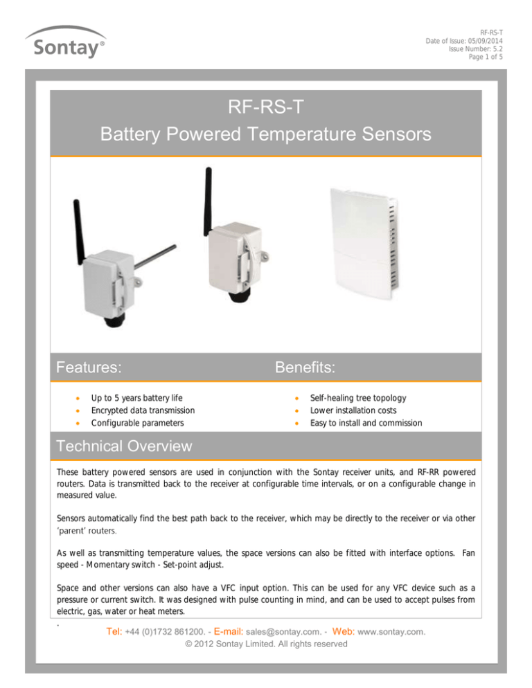
These battery powered sensors are used in conjunction with the Sontay receiver units, and RF-RR powered
routers. Data is transmitted back to the receiver at configurable time intervals, or on a configurable change in
measured value.
Sensors automatically find the best path back to the receiver, which may be directly to the receiver or via other
As well as transmitting temperature values, the space versions can also be fitted with interface options. Fan
speed - Momentary switch - Set-point adjust.
Space and other versions can also have a VFC input option. This can be used for any VFC device such as a
pressure or current switch. It was designed with pulse counting in mind, and can be used to accept pulses from
electric, gas, water or heat meters.
.
Tel: +44 (0)1732 861200. - E-mail: sales@sontay.com. - Web: www.sontay.com.
© 2012 Sontay Limited. All rights reserved
RF-RS-T
Date of Issue: 05/09/2014
Issue Number: 5.2
Page 2 of 5
Specification:
Part Codes:
Common specification:
Radio Output:
Frequency
2.4GHz
16 channels, automatically selected
Direct-sequence spread spectrum
Compliance
IEEE 802.15.4-2006
Data Encryption
AES 128
Power Output
0dBm
Temperature accuracy
±0.3°C
Country of origin
UK
RF-RS-T-1000
Space temperature sensor
Plant Housing:
Material
Dimensions
Battery (non-rechargeable):
Type
Life
Protection:
Snap-shut lid
-MS
-FS3
3-Position fan speed
-FS5
5-position fan speed
ABS (flame retardant type VO)
75 x 70 x 50mm
Momentary switch
-SP
3.6V 2/3 Li-SOCI2
>3 years (dependent on conf.)
Set-point adjust
-VFC
IP54
IP65 (see page 4 note 8)
Ambient:
Temperature
RH
Probe material
Probe dimensions:
(322 & 341)
(331)
(332)
(555)
Aerial Characteristics:
Gain
VSWR
Space Housing:
Material
Colour
Dimensions
Ambient:
Temperature
RH
Protection
Aerial Characteristics:
Gain
VSWR
Sensor options (add to part code)
-30 to +70°C
0 to 90%, non-condensing
PTFE (332) Stainless steel (others)
150mm x 6mm dia.
10mm dia.
40 x 16mm dia. cable 2 meters
30 x 6mm dia. cable 2-5 meters
Volt free input
RF-RS-T-322
Duct temperature sensor
RF-RS-T-342
Immersion temperature sensor
RF-RS-T-351
Clamp-on temperature sensor
RF-RS-T-331
Outside air temperature sensor
2.0dBi
<2:1
ABS (flame retardant)
Polished white finish
115 x 85 x 28mm
-10 to 60°C
0 to 90%, non-condensing
IP30
RF-RS-T-332
Outside air temperature with radiation shield
sensor
RF-RS-T-555-2
Flying lead temperature sensor, 2m cable
RF-RS-T-555-5
Flying lead temperature sensor, 5m cable
1.2dBi
1.5:1
The products referred to in this data sheet meet the
requirements of EU Directive 2004/108/E
Tel: +44 (0)1732 861200. - E-mail: sales@sontay.com. - Web: www.sontay.com.
© 2012 Sontay Limited. All rights reserved
RF-RS-T
Date of Issue: 05/09/2014
Issue Number: 5.2
Page 3 of 5
How It Works:
Data is transmitted back to the receiver at configurable time intervals, or on a configurable change in measured value. Each
sensor retains these configurations if the battery becomes discharged or requires replacement.
The sensors, routers and receiver automatically select which of the 16 transmission channels available gives the best radio
network performance, taking into account both signal strength and interference levels from adjacent channels and
equipment (such as Wi-Fi etc.) The sensors automatically find the best path back to the receiver, which may be directly to the
Aerial Orientation (plant sensor types);
For best results ensure that the main body of the aerial is vertical.
Installation:
Plant Sensor types:
1.
Remove all packaging from the sensor.
2.
Note the MAC address printed on the affixed label and note where this MAC address is installed.
3.
Mount the sensor in the required position (this will have been determined by the site survey tool, (see the quick
start guide and manual).
4.
See page 4 for individual installation depending on sensor type.
5.
Release the snap-fit lid by gently squeezing the locking tab and install the Li-SOCI2 battery, observing the correct
polarity.
6.
Snap shut the lid after the connections have been made if IP65 protection is required, secure the lid with two
screws provided.
7.
Ensure, at a minimum, that all routers and the receiver on the radio network are powered on, and allow about 5
minutes for the network to auto-commission before attempting to read values or make configuration changes.
Tel: +44 (0)1732 861200. - E-mail: sales@sontay.com. - Web: www.sontay.com.
© 2012 Sontay Limited. All rights reserved
RF-RS-T
Date of Issue: 05/09/2014
Issue Number: 5.2
Page 4 of 5
Installation (continued):
Duct
Select a location in the duct where the sensor probe will give a representative sample of the prevailing air condition.
Drill a 7mm diameter hole in the duct, then use the housing as a template mark the hole centres or use the
dimensions below), drill and fix the housing to the duct with the screws supplied.
24 mm
33 mm
Ø7 mm
Immersion
Select a location in the system where the liquid is to be measured, install pocket as per datasheet TT-PO.
Insert the probe into the pocket and secure with the grub screw provided within the pocket.
The immersion sensor must be used with a pocket, it is not designed for direct mounting.
Clamp-on
Select a location in the system where the liquid temperature is to be measured, where the brass lug will make good
contact with the surface of the pipe.
Secure the brass lug to the surface to the pipe using the clip provided. Wrap the clip around the pipe and place the
lug under the strap and tighten the clip. It is good practice to ensure that good contact is made between the lug
and the pipe, and apply insulation over the pipe and lug.
Outside air
Select a suitable location preferably on a north facing wall, ensuring that the sensor is away from direct sunlight
and any heat sources.
Outside air with radiation shield
Select a suitable location, the sensor has a radiation shield that helps minimizes error gains from direct sunlight.
Space Sensor Types:
1.
Remove all packaging from the sensor.
2.
Note the MAC address printed on the affixed label and note where this MAC address is installed.
3.
Mount the sensor in the required position (this will have been determined by the site survey tool, (see the quick
start guide and manual).
4.
Using the base as a template mark the hole centres and fix to the wall with suitable screws. Alternatively the base
plate can be mounted on to a conduit box or a standard recessed back box.
5.
Install the Li-SOCI2 battery, observing the correct polarity. To power on the unit, fit J400.
6.
Replace the housing to the base plate and re-fit the tamperproof screw through the lug at the bottom of the base
plate.
Tel: +44 (0)1732 861200. - E-mail: sales@sontay.com. - Web: www.sontay.com.
© 2012 Sontay Limited. All rights reserved
RF-RS-T
Date of Issue: 05/09/2014
Issue Number: 5.2
Page 5 of 5
Installation (continued):
7.
Ensure, at a minimum, that all routers and the receiver on the radio network are powered on, and allow about 5
minutes for the network to auto-commission before attempting to read values or make configuration changes.
Battery Fitting & Replacement:
The current battery level of a sensor can be monitored using the CMS software connected to the receiver. When a battery is
first installed, or when it is replaced, observe the correct polarity. Fitting the battery incorrectly may result in
permanent damage to the sensor. Remove the power jumper prior to removing a battery. After fitting a battery, replace
the power jumper while pressing the reset button. This resets the hours run counter for the battery.
NB Lithium-Thionyl Chloride batteries are not rechargeable, and should be stored in a clean, cool (not exceeding +30°C),
dry and ventilated area.
Disposal of Batteries - Warning! Fire, Explosion and Burn Hazard.
Do not recharge, short-circuit, crush, disassemble heat above 100°C (212°F), incinerate, or expose the battery contents to
water. Do not solder directly to the cell.
All batteries must be disposed of in accordance with EC Directive 2006/66/EC, amended by EU Directive 2008/12/EC.
Options:
Fan Speed Switch
Each time a change of position is detected it is transmitted immediately.
Momentary Switch
it
is transmitted immediately and the current output status is inverted (TRUE goes to FAUSE or FAUSE goes to TRUE) and stays
in the new state until the switch is pressed again.
Set-point Adjust
When the rotary dial when moved in any direction, it is transmitted immediately.
VFC
Used for any VFC digital input (such as a pressure switch or current switch), but it has also been designed with pulse
d feature us that the number of VFC
TRUE inputs is counted by the router or ED, and held in flash memory, so even if the ED or router doing the counting goes
by allowing the pulse counting
strategy to be updates when the ED or router comes back online meaning a pulse will never be missed. The ED or router can
hold the number of VFC TRUE conditions up to 4096, and is user resettable if required.
Whilst every effort has been made to ensure the accuracy of this specification, Sontay cannot accept responsibility for damage, injury,
loss or expense from errors or omissions. In the interest of technical improvement, this specification may be altered without notice.
Tel: +44 (0)1732 861200. - E-mail: sales@sontay.com. - Web: www.sontay.com.
© 2012 Sontay Limited. All rights reserved


