Kit Instructions - Jameco Electronics

Electronic Organ
PART NO. 2177918
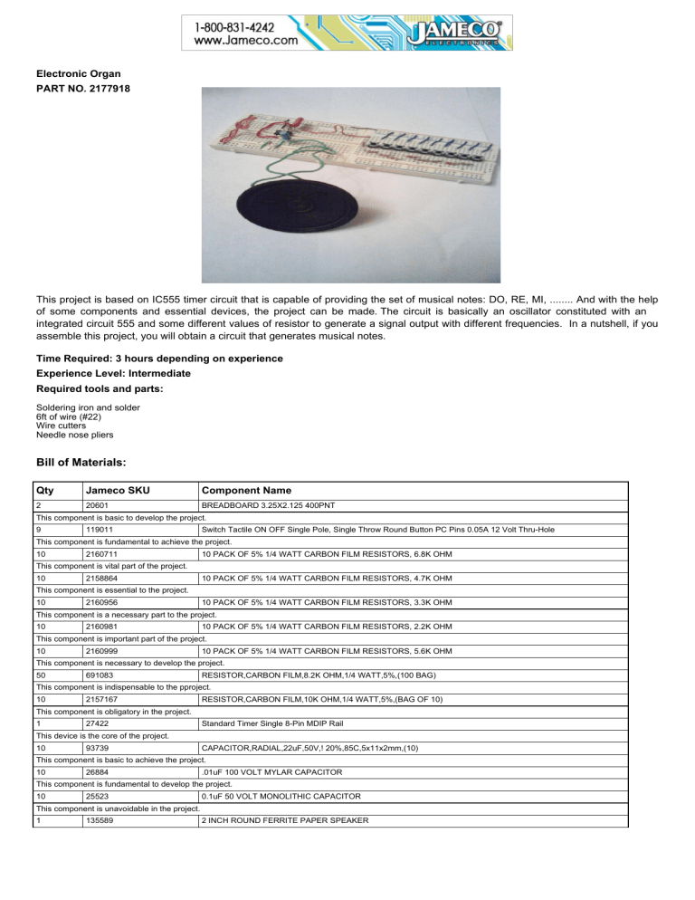
This project is based on IC555 timer circuit that is capable of providing the set of musical notes: DO, RE, MI, ........ And with the help of some components and essential devices, the project can be made.
The circuit is basically an oscillator constituted with an integrated circuit 555 and some different values of resistor to generate a signal output with different frequencies. In a nutshell, if you assemble this project, you will obtain a circuit WKDW generates musical notes.
Time Required: 3 hours depending on experience
Experience Level: Intermediate
Required tools and parts:
Soldering iron and solder
6ft of wire (#22)
Wire cutters
Needle nose pliers
Bill of Materials:
Qty Jameco SKU Component Name
2 20601 BREADBOARD 3.25X2.125 400PNT
This component is basic to develop the project.
9 119011 Switch Tactile ON OFF Single Pole, Single Throw Round Button PC Pins 0.05A 12 Volt Thru-Hole
This component is fundamental to achieve the project.
2160711
This component is vital part of the project.
10 PACK OF 5% 1/4 WATT CARBON FILM RESISTORS, 6.8K OHM
2158864
This component is essential to the project.
10 PACK OF 5% 1/4 WATT CARBON FILM RESISTORS, 4.7K OHM
2160956 10 PACK OF 5% 1/4 WATT CARBON FILM RESISTORS, 3.3K OHM
This component is a necessary part to the project.
2160981 10 PACK OF 5% 1/4 WATT CARBON FILM RESISTORS, 2.2K OHM
This component is important part of the project.
2160999 10 PACK OF 5% 1/4 WATT CARBON FILM RESISTORS, 5.6K OHM
This component is necessary to develop the project.
691083 RESISTOR,CARBON FILM,8.2K OHM,1/4 WATT,5%,(100 BAG)
This component is indispensable to the pproject.
2157167
This component is obligatory in the project.
RESISTOR,CARBON FILM,10K OHM,1/4 WATT,5%,(BAG OF 10)
27422
This device is the core of the project.
Standard Timer Single 8-Pin MDIP Rail
93739 CAPACITOR,RADIAL,22uF,50V,! 20%,85C,5x11x2mm,(10)
This component is basic to achieve the project.
26884 .01uF 100 VOLT MYLAR CAPACITOR
This component is fundamental to develop the project.
25523
This component is unavoidable in the project.
0.1uF 50 VOLT MONOLITHIC CAPACITOR
135589 2 INCH ROUND FERRITE PAPER SPEAKER
Step 1 - Materials for your Electronic Organ
In this step, you will identify the following parts:
2 Breadboard 3.25" X 2.125" 400 Point
9 Switch Tactile OFF-ON Single Pole
2 Resistors of 6.8K, 1/4W
2 Resistors of 4.7K, 1/4W
2 Resistors of 3.3K, 1/4W
2 Resistors of 2.2K, 1/4W
1 Resistor of 5.6K, 1/4W
1 Resistor of 8.2K, 1/4W
1 Resistor of 10K, 1/4W
1 IC555 Timer
1 Electrolytic Capacitor of 22 X F, 50V
1 Capacitor of 0.01
X F, 100V
1 Capacitor of 0.1
X F, 50V
1 Speaker of 8 RKP , 0.25W
Step 2 - Identify the Tactile Switch H s
You will need to identify the pins of each tactile switch of your project.
Step 3 - Install the Tactile Switches
Mount the tactile switches and identify their pins (A and D) those to connect with the rest of the circuit.
Step 4 - Connect the Pin D to Terminal Positive
Connecting to terminal positive of your protoboard each pin D of each tactile switch.
Step 5 - Identify the Pin A of the Tactile Switches
Identify the pin D of each tactile switch.
Step 6 - Connect the Resistors
All resistors should be connected to each pin A of each tactile switch.
Step 7 - Identify the Pins of the IC555 Timer
Mount your IC555 on the other breadboard.
Step 8 - Connect the Resistor of 10K
The resistor of 10k should be connected to pins 6 and 7 of the IC555 timer.
Step 9 - Connect Pins 2 and 6 of the IC555
The pins 2 and 6 of the IC555 timer should be interconnected.
Step 10 - Install the Capacitor of 0.1 uF
Between terminal negative and pin 2 of the integrated circuit should be connected the capacitor of 0.1 uF.
Step 11 - Connect the Capacitor of 0.01 uF
Between the pin 5 of the IC555 timer and terminal negative of the circuit, you should connect the capacitor of 0.01 uF.
Step 12 - Connect the Resistor of 6.8K
Connect the resistor of 6.8K to pin7 of the IC555 timer and the other end will wait to be connected to the resistor of 4.7K of the other breadboard with the tactile switches. And the pin 1 of IC555 timer should be connected to terminal negative of the circuit.
Step 13 - Connect Pins 4 and 8 of the IC555
Connect Pins 4 and 8 of the IC555 to terminal positive.
Step 14 - Interconnect each one of the Polarities
Interconnect each polarity correctly, i.e., connect the terminal positive with the terminal positive. Then, connect the terminal negative with the terminal negative.
Step 15 - Connect the Electrolytic Capacitor of 22 uF
Connect the Electrolytic Capacitor of 22 uF between the pin 3 of the IC555 timer and the speaker. You should connect the pin 3 with the terminal positive of the capacitor, and the terminal negative of this with the terminal speaker later.
Step 16 - Connect the Speaker
Connect the speaker between the terminal negative of the circuit and the terminal negative of the electrolytic capacitor of 22 uF.
Step 17 - Complete your Project
Complete your project by joining both breadboards that with the tactile switch and the other with the Integrated circuit. Then, you need to connect the terminal positives of both breadboards and the end isn't connect of the resistor of 6.8K to the resistor of 4.7K.


