NomNom FX Filter DIY Build Guide
N O M N O M
FX Type: Filter
2015 edition
Based on the MXR Phase 90™
© 2015 madbeanpedals
Download the previous version documentation here: http://www.madbeanpedals.com/projects/NomNom/NomNom.zip
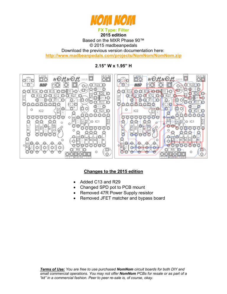
2.15” W x 1.95” H
Changes to the 2015 edition
· Added C13 and R29
· Changed SPD pot to PCB mount
· Removed 47R Power Supply resistor
· Removed JFET matcher and bypass board
Terms of Use: You are free to use purchased NomNom circuit boards for both DIY and small commercial operations. You may not offer NomNom PCBs for resale or as part of a
“kit” in a commercial fashion. Peer to peer resale is, of course, okay.
R22
R23
R24
R25
R26
R27
R28
R29
R14
R15
R16
R17
R18
R19
R20
R21
R7
R8
R9
R10
R11
R12
R13
Resistors
R1
R2
10k
470k
R3
R4
R5
R6
150k
150k
56k
150k
10k
10k
22k
10k
10k
22k
10k
150k
4k7
470k
150k
4k7
10k
1M
***
10k
22k
10k
10k
22k
22k
150k
3M9
B.O.M.
C1
C2
C3
C4
C5
C6
C7
C8
C9
C10
C11
C12
C13
Caps
10n
50n
50n
50n
50n
50n
50n
15uF
10n
100uF
100n
22uF
**
D1
D2
Diodes
1N5817
5.1v Zener
Transistors
Q1 2N5087
Q2 Q5 2N5457
IC
IC1
IC2
TL072
TL074
Switch
NOM SPDT
Trimpots
T1
T2
250k
25k
SPD
Pot
500kC
· 50n is a less common value in caps these days (at least in the U.S.). Use 47n instead.
· The NomNom is laid out for 2N5457 transistors since they are still very common and work equally well in the phase circuit. If you want to use the original 2N5952, you will need to flip the transistors 180° on the PCB since the 2N5952 have the opposite pinout of the 2N5457.
· 2N5087 is indicated for Q1 since it is also very common. You can use the original 2N4125 if you have it or even a 2N3906. All three have the same pinout.
· If you do not have a 15uF cap for C8, use 10uF and add a 4u7 cap to C13 to approximate
15uF. Leave C13 empty if you are using 15uF for C8.
2
Value QTY
4k7
10k
22k
2
10
5
56k
150k
470k
1M
1
6
2
1
3M9
10n
50n
100n
15uF
22uF
100uF
1N5817
1
1
1
1
5.1v Zener 1
2N5087
2N5457
TL072
TL074
1
4
1
1
1
2
6
1
SPDT
250k
25k
500kC
Shopping List
Type
Carbon / Metal Film
Carbon / Metal Film
Carbon / Metal Film
Carbon / Metal Film
Carbon / Metal Film
Carbon / Metal Film
Carbon / Metal Film
Carbon / Metal Film
Film
Film
Film
Electrolytic
Electrolytic
Electrolytic
1
1
On/On (or SPST)
Bourns 3362P
1 Bourns 3362P
1 PCB Mount (short pin)
Rating
1/4W
1/4W
1/4W
1/4W
1/4W
1/4W
1/4W
1/4W
16v or more
16v or more
16v or more
16v or more
16v or more
16v or more
1/2W or 1W
16mm
3
1590B Enclosure (TopDown View)
4.43” W x 6.46” H
Download the Photoshop file used to create this template here: http://www.madbeanpedals.com/projects/NomNom/NomNom_DRILL.zip
125B Enclosure (TopDown View)
5.52” W x 7.65” H
6
Wiring Diagram
7
The NomNom is an MXR Phase 90™ (script logo) clone for the 1590B (or 125B). Building the
NomNom requires the use of four matched JFETs to achieve proper phase.
· SPD – Controls the rate of the LFO that sweeps the circuit through the phase stages from slow to fast.
· NOM – This switch enables feedback which intensifies the phase effect.
· T1 – This trimmer is used to calibrate the phase effect.
· T2 – This trimmer sets the maximum amount of feedback when the NOM switch is engaged.
An important consideration: Do you want to match your JFETs or pay someone else to do it?
This is a good question to ask before you start. Finding four well matched JFETs for the NomNom (or any similar phaser) is going to require a healthy supply of transistors. You should have at least 25 transistors on hand before even considering doing it yourself and it would be much better to have 50 or more. The Vgs characteristic (the thing we are comparing) varies widely from device to device and it is entirely possible to go through a few handfuls to find the right ones.
The good news is that if you have a sufficient amount of transistors, you will likely find several pairs or quads that will work for future phaser builds. However, if the NomNom is the only phaser you are ever going to build, it might be better to purchase prematched transistors and skip the matcher PCB altogether. If this is the route you chose, guitarpcb.com has a set of four matched 2N5952 transistors for $9.95 at the time of this writing. By comparison, 50 2N5457 or 2N5952 transistors from smallbear will cost you $25. Still, you might find cheaper lots of these on eBay so it is worth checking out.
See pg.10 for more info on how to match transistors for the Nom Nom.
Calibrating
Once you have populated the main PCB, attached the SPD pot, NOM switch and connection wires it’s time to load this thing up onto your testing rig for calibrating. You DO have a testing rig…right?
Well, allow me to retort. You needs one. Unless this is the only pedal you are ever going to build, every rocker should have a prototyping rig to Rock It Before You Box It. Need help on making one?
Here’s the science: http://www.madbeanpedals.com/forum/index.php?topic=1140.0
Set the T1 and T2 trimmers about halfway up. Set the SPD pot halfway, too and leave the NOM switch OFF. Throw some fat chords out on your guitar and begin tweaking the T1 trimmer. What you are trying to achieve is a setting that results in the maximum amount of phase depth with minimum noise. What’s happening here is that the trimmer is adjusting the bias voltage created by R27 and D2 via the current limiting resistor of R28. Put simply, you are dialing in the right voltage to allow the LFO to sweep the guitar signal through the four phase stages for the most pleasant sounding result. Try setting the SPD pot up and down further and continue tweaking. It is actually very simple and should only take a minute or two to find the right setting.
Once you have T1 dialed in turn the NOM switch on to enable feedback. Adjust T2 to taste. Counter clockwise settings produce more feedback and vice versa. You may find the lowest setting on T2 produces some selfoscillation and this should be avoided. Personally, I prefer the feedback setting a bit higher so it is not too intense, so around the middle of the trimmer is just right for me.
8
If for some reason you are not getting any phasing at all, you need to start standard debug procedures. Check voltages on the ICs and transistors ensure that all transistors are oriented correctly; all joints are properly soldered, and so on. I have read that in some cases D2 might need to be replaced with a 4.7vZener if you are not getting the phasing effect, however in practice I have never experienced this. Still, it is something to keep in mind if all other possibilities are eliminated.
If you want a different flavor of phase, you can substitute the phase caps for the values used in the
Univibe. It won’t magically turn your NomNom into a Univibe, but it will get you in the ballpark.
Obviously you will want to socket these caps so you can revert to the traditional values if you want.
Make the following changes: C3: 15n, C4: 220n, C5: 470pF, C6: 4n7
Double Extra Bonus #2: try the same values in a different order. Ex: 470pF, 4n7, 15n, 220n and so on.
IC1
1 4.25
2 4.25
3 4.05
4 0
5 varies
6 varies
7 varies
8 8.67
Voltages
IC1
1
2
3
4.26
4.29
4.29
4
5
6
7
8
9
8.68
4.25
4.7
4.42
4.18
4.24
10 4.26
11 0
12 4.25
13 4.25
14 4.26
9.4 One Spot supply
These voltages were taken from the 2014 NomNom which included a 47R inline resistor on the power supply. Since this was removed from the 2015 edition your voltages will likely read a little higher. Keep in mind that some voltage readings will also depend on where you have T1 set. However, these readings should give you the ballpark estimate on what to expect.
9
Matching Transistors
Read about how JFET matching is done here (courtesy of RG Keen): http://www.geofex.com/Article_Folders/fetmatch/fetmatch.htm
You can use this schematic to breadboard the transistor matching circuit or etch your own PCB. DUT stands for “Device Under Test” (the transistor from which you take the Vgs reading).
0.83”W x 0.75”H
· Connect the RED lead of your DMM to D1 and the BLACK lead to D2. Set your DMM for a DC voltage reading (FYI it doesn’t matter which lead you connect to the D1/D2 pads as long as you do it consistently from device to device).
· Place the first transistor into the DUT socket. A 2N5457 goes in as is shown on the PCB. A
2N5952 should be turned in the opposite direction.
· Measure the voltage reading and record it on a piece of paper. Take the transistor out and place it next to the written record.
· Repeat this process: load a transistor, make a recording, and place the transistor next to the recording. Keep doing this until you start to see matches.
· You want to find the closest matching voltage readings on these transistors. At least within 5% of one another, although I generally shoot for 1% or less. So, if a device reads 0.75vDC, I would look for another one that measures 0.74 to 0.76v.
· You may find several matches over different groups of readings. If so, great! Gather them up in groups of two or four and save them for future builds. Set aside your four best matched transistors for the NomNom.
10
Using an LED
There are two ways you can use an LED indicator for the Speed control.
Method 1 – Make R29 a 1k resistor. Wire the “LS” pad to the anode of a 3 or 5mm diffused LED.
Wire the cathode of that LED to ground. This method will show a square wave output so it will blink on and off.
Method 2 – Make R29 a 1M resistor. Wire the “LS” pad to the circuit shown below. This will give the
LED some ramp up and down on its illumination so it is not quite so “square”.
0.71”W x 0.38” H
11

