Flanged Connections for steel pipes
advertisement

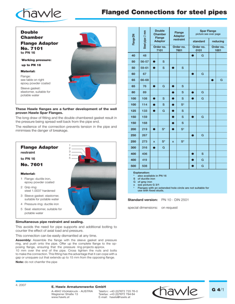
Flanged Connections for steel pipes Working pressure: up to PN 16 Material: Flange: see table on right epoxy powder coated Sleeve gasket: elastomer, suitable for potable water These Hawle flanges are a further development of the well proven Hawle Spar Flanges. The long draw of fitting and the double chambered gasket result in the pressure being spread well back from the pipe end. The resilience of the connection prevents tension in the pipe and minimises the danger of breakage. Flange Adaptor restraint to PN 16 1 2 3 4 5 No. 7601 Material: 1 Flange: ductile iron, epoxy powder coated 2 Grip ring: steel 1.0037 hardened 3 Sleeve gasket: elastomer, suitable for potable water 4 Pressure ring: ductile iron 5 Seal: elastomer, suitable for potable water Flange Adaptor restraint Order no. 7101 Order no. 7601 Steel pipe Ø mm to PN 16 Double Chamber Flange Adaptor Flange DN Double Chamber Flange Adaptor No. 7101 40 48 50 56-57 S 50 59-61 S 60 67 65 66-68 65 76 80 89 100 108 100 114 125 133 150 Spar Flange picture see over page standard reducing Order no. 0101 Order no. 1001 G G S S S G S S G S S¹ G S 159 S G 150 168 S 200 219 S¹ 250 267 G 250 273 x S* 300 316 G 400 406 S 400 419 G 500 508 G G S* x G S* Explanation: * also available in PN 16 S of ductile iron G of grey iron x see picture G 3/1 ¹ Flanges with an extended hole circle are not suitable for use with fixed studs. Standard version: PN 10 - DIN 2501 special dimensions: on request Simultaneous pipe restraint and sealing. This avoids the need for pipe supports and additional bolting to counter the effect of axial load and pressure. This connection can be easily dismantled at any time. Assembly: Assemble the flange with the sleeve gasket and pressure ring, and push onto the pipe. Offer up the complete flange to the opposing flange, ensuring that the pressure ring projects approx. 10 mm over the end of the pipe. Cross tighten the nuts and bolts to make the connection. This fitting has the advantage that it can cope with a gap or unsquare cut that extends up to 15 mm from the opposing flange. Note: do not chamfer the pipe 4. 2007 G 4/1 Flanged Connections for steel pipes No. 7101 No. 0101 No. 1001 No. 7101 / No. 0101 Flange DN Steel Pipe Ø mm 40 50 50 60 65 80 100 100 125 150 200 250 300 400 400 500 48 56-57 59/61 67 76 89 108 114 133 159 219 267 316 406 419 508 D - No. 7101 0101 150 165 165 175 185 220 220 250 200 220 285 340 400 455 565 565 690 K 110 125 125 135 145 160 180 180 210 240 295 350 400 515 515 620 Bolts b - No. ˜ L (assembled) 7101 7101 26 26 54 54 28 56 25 23 33 63 63 64 30 71 49 82 Weight kg - No. 0101 Qty. Thread 30 4 4 4 4 4 8 8 8 8 8 8 12 12 16 16 20 M 16 M 16 M 16 M 16 M 16 M 16 M 16 M 16 M 16 M 20 M 20 M 20 M 20 M 24 M 24 M 24 37 37 38 45 48 60 60 76 7101 0101 0,9 2,6 2,6 2,5 3,5 3,8 3,5 6,8 3,2 4,4 7,5 8,6 14,5 18,5 22,0 36,5 43,0 No. 1001 Bolts Flange DN Steel pipe Ø mm D K ˜L with reducer Qty. Thread Weight kg 65 66-68 185 145 60 4 M 16 5,0 Weight including reducing ring with reducing ring No. 7601 No. 7601 Steel pipe Ø mm D K b ˜L (unassembled) Qty. Thread Weight kg 50 65 80 100 100 125 150 150 200 60 76 89 108 114 133 159 168 219 165 185 200 220 220 250 285 285 340 125 145 160 180 180 210 240 240 295 39 38 39 39 44 39 49 52 52 61 61 67 69 69 69 73 73 81 4 4 8 8 8 8 8 8 8 M 16 M 16 M 16 M 16 M 16 M 16 M 20 M 20 M 20 2,7 3,4 3,9 4,6 4,4 5,8 7,8 7,3 10,0 Illustrations, technical data, dimensions and weights are subject to alteration without notice. G 4/2 Bolts Flange DN 4. 2007


