Voltage, Current, Resistance and Ohm`s Law
advertisement

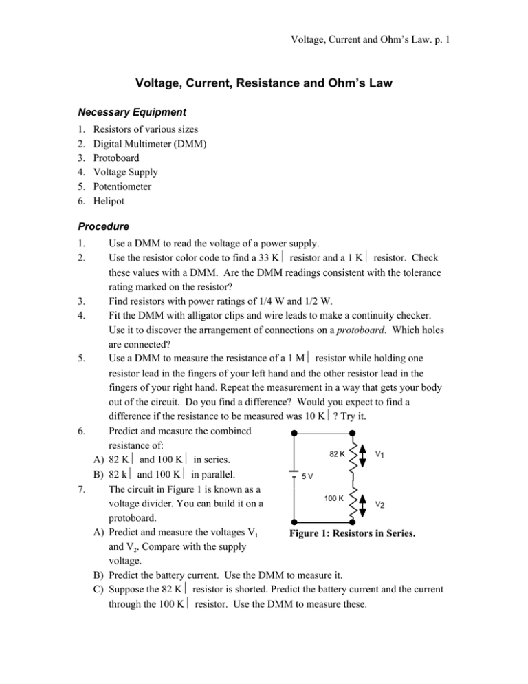
Voltage, Current and Ohm’s Law. p. 1 Voltage, Current, Resistance and Ohm’s Law Necessary Equipment 1. 2. 3. 4. 5. 6. Resistors of various sizes Digital Multimeter (DMM) Protoboard Voltage Supply Potentiometer Helipot Procedure 1. 2. 3. 4. 5. 6. A) B) 7. A) B) C) Use a DMM to read the voltage of a power supply. Use the resistor color code to find a 33 KΩ resistor and a 1 KΩ resistor. Check these values with a DMM. Are the DMM readings consistent with the tolerance rating marked on the resistor? Find resistors with power ratings of 1/4 W and 1/2 W. Fit the DMM with alligator clips and wire leads to make a continuity checker. Use it to discover the arrangement of connections on a protoboard. Which holes are connected? Use a DMM to measure the resistance of a 1 MΩ resistor while holding one resistor lead in the fingers of your left hand and the other resistor lead in the fingers of your right hand. Repeat the measurement in a way that gets your body out of the circuit. Do you find a difference? Would you expect to find a difference if the resistance to be measured was 10 KΩ? Try it. Predict and measure the combined resistance of: 82 K V1 82 KΩ and 100 KΩ in series. 82 kΩ and 100 KΩ in parallel. 5V The circuit in Figure 1 is known as a 100 K V2 voltage divider. You can build it on a protoboard. Predict and measure the voltages V1 Figure 1: Resistors in Series. and V2. Compare with the supply voltage. Predict the battery current. Use the DMM to measure it. Suppose the 82 KΩ resistor is shorted. Predict the battery current and the current through the 100 KΩ resistor. Use the DMM to measure these. Voltage, Current and Ohm’s Law. p. 2 8. 9. 10. 11. 12. Figure 2 shows an open circuit. What is the current through the ammeter? What is the voltage at point P? Figure 3 shows a voltage divider that A is loaded by a load resistor RL. Predict how the voltage V2 changes if 82 KΩ RL = 1 MΩ. Measure it. Predict how the voltage V2 changes if RL = 330 KΩ and measure it. P A potentiometer (pot) has three terminals. Use a DMM to identify Figure 2: Open Circuit. the terminal for the moveable tap on a standard rotary pot. Which terminals are connected together for maximum clockwise rotation? For maximum CCW rotation? Adjust the pot so that the resistances of the two sides are equal. Show by measurements that this pot is now a V2 82 KΩ voltage divider that divides the voltage by two. Does it matter what the resistance of 5V 100 KΩ RL the pot is? Use a DMM to identify the moveable tap on a Helipot. Figure 3: Voltage Divider.


