User Training, Power Meter
advertisement

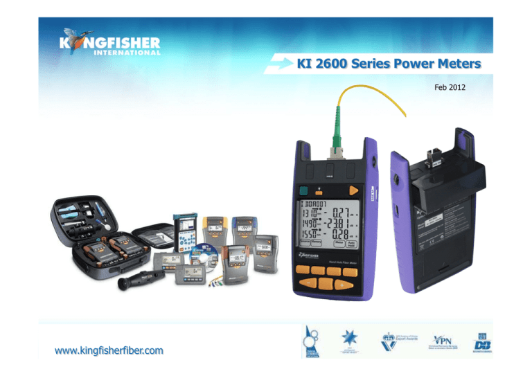
KI 2600 Series Power Meters Feb 2012 1 www.kingfisherfiber.com 20080825 Course Contents 1. 2. 3. 4. 5. General Features -3 Keypad -4 Operation -5 Menu System -11 Modes of operation -14 6. Select Display Measurement unit -22 7. Memory Operation -29 8. Other Features -31 9. Firmware - 38 10. Instrument care -41 2 1./ General Features Autotest Calibrated at multiple wavelengths Industry standard connector adaptors Large high contrast LCD display 3 Power - Battery or micro USB Memory – Internal or USB Time date stamp Text ID Test tone detection 2./ Keypad Backlight Remove Connector Connector Cover On/Off Lanyard holder Store External Power & Computer interface USB port for memory stick Memory, Text ID, Date [F1-F4] [F1-F4] Toggle Centre 4 3./ Operation 1. Select / determine test cord configuration 2. Fit adaptor 3. Fit batteries 4. Turn On 5. Menu System 5 3.1 / Select test cord connector Identify fibre type required for test cord and configuration required. Supplied with :- SC connector as standard Unlike sources, power meters accept both PC and APC connectors. 6 To fit / change an adaptor / connector • • • • • Locate quick release button on front of instrument at base of connector housing Lightly push and hold latch button in Slot to Pull out existing adaptor outside Release latch button. Fit new adaptor. F1 7 F2 F3 F4 3.2 / Fit Batteries Unclip Battery compartment cover at rear of instrument Note: battery +Ve terminal spring orientation Instrument time setting holds for approx 7 seconds during change over. Alkaline battery run time approx 1,000 hours Early Models Current Models 8 Batterytype typeconfiguration configuration Battery To enable rechargeable batteries to be internally charged this feature must be enabled by means of an 0.1” pitch shorting pin. or Alkaline Battery configurations Instrument supplied in this configuration. Rechargeable Battery configuration 9 3.3 / Turn On • 10 minutes auto off • Permanent operation • Low battery indicator To turn On / Off: Push the Green [On/Off] button Per m To Defeat auto time out. Press [On/Off] & hold for 3 seconds. M e m or y Instrument will beep twice. ‘Perm’ will display on the upper RHS of the LCD. 10 F1 F2 Meter F3 F4 4./ Menu System Memory Meter Top level Menu 11 4.1/ Memory Menu Memory Home Return to Top Level Menu Memory Mode Read Memory Select dBm, dBr, Watt 12 4.2/ Meter Menu Meter Home Meter Mode Set Ref Return to Top Level Menu In dBr mode, Set 0 dBr Select dBm, dBr, Watt 13 Hold Hold the display 5./ Modes of Operation 1) Autotest: automatically toggles between all wavelengths Preferred mode for loss testing as testing time is greatly reduced. Minimises error as meter always displays correct wavelength. 2) Manual: Single wavelength operation Preferred mode for level monitoring. 3) Test Tone: Displays incoming modulation frequency 4) Slow Mode: Displays power level in the presence of test tone or low level modulation 4) KITS software: Under software control 14 5.1 / Autotest Simplest mode for loss testing When receiving light from a compliant source operating in Autotest mode, the meter will auto toggle between wavelengths. Power meter receives data which contains wavelength, source serial number and nominal source output power. If power meter not calibrated at an incoming wavelength it will ignore it but remain in sync with other wavelengths. If incoming power level too low at a particular wavelength it will ignore it but remain in sync with other wavelengths. 15 Autotest Display When receiving light from a source operating in Autotest mode: Screen displays up to 3 wavelengths at a time. Screen toggles if more than 3 wavelengths being received Au t o Pe r m nm d Bm nm d Bm nm Ho m e d Bm M e te r M od e Se t Re f 16 Au t o H old 5.2 / Manual Mode To enter Meter mode Press [F3], Meter Pe rm Pe r m nm Mem ory Hom e F1 F2 dBm M et e r F3 Se t Ref Met er Mode Aut o Hol d F4 F1 17 F2 F3 F4 Select Wavelength To select wavelength Toggle [-] & [+]. Note: Wavelength toggle is not circular Most meters have the common wavelengths grouped together for speed of access when used in manual mode. E.g. 850, 1300, 1310, 1550, 1625 nm are together Pe r m nm Hom e F1 18 Set Ref F2 dBm Met er Mode F3 Aut o Hol d F4 5.3 / Test Tone When receiving test tone or low level modulation Power meter displays modulated frequency and beeps To measure power in the presence of tone, SlowMode is used. To defeat Beeping:- Hz At Turn-On hold [F2]. Hz Hz 19 Hz 5.4/ SlowMode SlowMode: Used when it is necessary to measure power in the presence of test tone or low level modulation e.g. low data rate SCADA transmissions. • • When active, the meters sample interval is increased. The symbol ” ” is displayed when active. SCADA: supervisory control and data acquisition In the presence of Test Tone: • To activate, Press [F4] • To turn Off, Press and hold [F3] (Meter Mode) & then press [F4]. In normal Mode: • To activate, Press and hold [F3] (Meter Mode) & then press [F4]. • To turn Off, Press and hold [F3] (Meter Mode) & then press [F4]. Per m Perm Hz nm Hom e 20 Se t Re f dBm Met er Mod e Hol d 5.5 / KITS control Direct Interface to - KITS™ Testing & Reporting software Instrument under computer control • Click results directly into workbook • Standards based & user definable analysis • Data Logging • Memory extract to KITS or CSV file • Familiar Excel™ User Interface • Inbuilt multi language support • Customisable reports 21 6./ Select Display Measurement unit Absolute dBm / Relative dBr mode / Linear W mode Absolute Mode: Measure actual power level at a particular location in decibels – dBm Relative Mode: Measure power level ‘relative’ to a particular location in decibels – dBr Linear Mode: Measure power level at a particular location in watts - W 22 Toggle Absolute/Relative/Linear Repeated pressing of Meter Mode button [F3] , toggles through Absolute – dBm, Relative - dBr and Linear - W modes. nm d Bm Pe r m nm nm Hom e F1 Set Ref F2 dB R dBm Met er Mode F3 Aut o Hold nm F4 23 uW 6.1 / Set Reference If not in dBr mode, press [F3], Meter Mode as required to enter dBr mode. • Press and hold [F2] Set Ref for approx 2 seconds. • Meter will beep 4 times and zero Aut o Aut o Perm Perm nm dBm nm F1 Se t Re f F2 F3 dBm nm dBm Met er Mod e dBm nm dBm nm Hom e nm Aut o Hol d Home F4 F1 24 Set Ref F2 dBm Met er Mode F3 Aut o Hold F4 Source -6.99 dBm 2x 10⁻² mW Cabling under test Meter -47.71 dBm 1.67x10⁻⁵ mW -40.72 dBr 0 dBr Loss = Send – Receive dB => Loss = (-6.99) – (-47.71) = 40.72 dB 25 7./ Memory Operation 1) Memory clear 2) Memory store 3) Memory recall 4) Dump to USB memory 26 7.1/ Memory Clear If not in Memory mode, Press [F2] , Memory To clear Memory: • Press and hold [Toggle Centre] then press [On/Off] • ‘CLr’ will be displayed for a few seconds. • Stored Text ID Tags are not cleared by this procedure. Aut o m em Perm Per m m em nm 2 dB R nm dB R nm dB R Mem ory Mem ory Hom e F1 Hom e Mod e F2 F3 F4 1 F1 27 Mod e F2 F3 F4 7.2/ Memory Store To Store: • Press [], Store • • Instrument will beep and Memory increment Stored Memory location displayed whilst button depressed. Per m m em To save to to a specific Memory location: • Toggle [-] & [+] to desired memory. • Press and hold [F2], Memory for 3 seconds. • • Instrument will beep once new location is set. Future Memory saves continue from this location. 28 Mem ory Hom e F1 Mod e F2 F3 F4 7.3/ Memory Recall If not in Memory mode, Press [F2] , Memory • To view Memory, press [F4] • To toggle between dBm, dBr and W, press [F3] • For data stored in Autotest mode, ‘auto’ displays • To toggle memory press [-] or [+] • To exit memory mode, press [F1] , Home Aut o nm m em nm F1 dB R F3 F4 nm uW nm uW nm uW Mem ory Mem ory Hom e Mod e F2 dB R nm dBm Mem or y Hom e Per m m em dB R dBm nm Per m nm dBm nm Aut o Aut o Perm m em F1 Hom e Mod e F2 F3 F4 Toggling stored data metrics 29 F1 Mod e F2 F3 F4 7.4/ Dump to USB memory Must be in Memory mode to detect USB memory stick. To enter Memory Mode: • Press [F2], Memory. or • Press [F1], Home, then press [F2], Memory. USB m em Insert USB memory stick. • ‘USB’ will show on the LCD • If not in Memory mode, Press [F2] , Memory • Press [] to start Memory dump. • ‘WAIT’ will display whilst USB memory configured. • A buzzer will sound during memory dump. • Do not remove USB stick until ‘USB’ has stopped flashing. Memory Image from KI2X00 SN: 202 Mem 1 2 3 4 Time in 24h format. Wavelengths in nm. Optical Power values in dBm. Date Time Type 7/02/32 11:57 Meter 7/02/32 12:44 2WlAuto 7/02/32 12:44 2WlAuto 7/02/32 12:44 2WlAuto ID_Tag RemSN Wl1 Pwr1 Ref1 Nom1 Wl2 Pwr2 Ref2 Nom2 AAAA022 0 1610 -19.36 -19.36 AAAA023 11216 1310 -18.88 0.3 -7 1550 -19.33 0.4 -7 AAAA024 11216 1310 -18.88 0.3 -7 1550 -19.33 0.4 -7 AAAA025 11216 1310 -18.88 0.3 -7 1550 -19.33 0.4 -7 30 nm dBm nm dBm Mem or y Hom e F1 Mod e F2 F3 F4 8./ Other features 1) Set date/Time 2) Min-Max Recording 3) Cable text ID 31 8.1/ Set Date-Time Date Time setting order is:Hour -> Minute ->Month -> Date -> Year Turn On instrument while holding down [Toggle Centre] • To modify the selected time/date, press [-] or [+] To select next/last time and date item: • Press [Toggle Centre] or [F3] , Mode, next item will flash. • To Save & Exit, press [F2] , Memory. • To exit without saving, press [F1] , Home. Mem ory Hom e F1 Loss of Power. • If batteries are removed for longer than about 20 seconds, Date-Time settings are lost 32 Mod e F2 F3 F4 8.2/ Min – Max recording Max/Min display mode: • Maximum & Minimum power meter values are continuously recorded. • Function disabled in Autotest. To activate / Hide: • Press [-] and [+] simultaneously. Au t o Per m Per m dBm max nm nm dBm dBm dBm m in To • • • Reset: Change wavelength. Set Reference. Power Off/On. Hom e F1 33 Se t Re f F2 Met er Mod e F3 Hol d F4 Hom e F1 Se t Re f F2 Met er Mod e F3 Hol d F4 8.3/ Cable/ Text ID tag Text ID: Used in conjunction with Memory save to identify a location or a cable. • Max 20 individual text ID tags • Format is 4 Alphanumeric letters, followed by 3 digits • The last 3 digits Auto increment. • e.g. CLEM 062, CLEM 063 etc etc. Au t o Pe r m nm d Bm nm d Bm nm Ho m e d Bm Meter M od e Se t Re f 34 Au t o H o ld Create Text / Location ID If not in meter mode, press [F3], Meter. • Press [Toggle centre] , then [F4] • A new ID tag AAAA 001 will display, the active character will flash. • • Toggle [-] and [+] to select an alphanumeric character. Press [Toggle centre] to select. • • To Save & Exit, press [F2] , Memory. To exit without saving, press [F1] , Home. nm nm dBm Hom e M em or y F2 F1 1 35 Mod e F3 F4 2 Using Text / Location IDs If not in meter mode, press [F3], Meter. • Press [Toggle centre] , Text/Location ID tag will flash. • Press [-] or [+] to select. • • To Save & Exit, press [F2] , Memory. To exit without saving, press [F1] , Home. nm Hom e F1 nm M em or y Mod e F2 F3 36 Hom e F4 F1 M em or y Mod e F2 F3 F4 Delete Text / Location ID If • • • not in meter mode, press [F3], Meter. Press [Toggle centre] Press [-] or [+] to select stored ID to be deleted. Press [F3], then [F4] , • Location ID replaced by a row of flashing dots/dashes. • • To confirm deletion, press F2, Memory. To exit without changing press F1, Home. Pe r m Pe r m nm Ho m e Me m ory nm d Bm M od e Hold Ho m e 37 Me m ory d Bm M od e Hold 9./ Firmware The KI2000 series Firmware can be end-user upgraded. To update Firmware:1. Instrument Firmware must not be r0.11. This version only can not update. 2. KI2000 USB device driver software must be installed. 38 9.1/ Check version The instrument Firmware variant can be checked during turn On. • Hold down [F4] and turn On • The instrument serial number and Firmware version is displayed whilst [F4] is held. Serial Number (SN) Meter Release number Firmware nm dBm 39 9.2/ Procedure 1. Download and extract the Firmware Update from Kingfisher web site 2. Connect instrument to computer 3. Run Firmware Update program. • KI2000 programmer vx.xx.exe 4. Follow procedures as detailed in the Firmware Update instruction PDF • KI2000 Programming Instructions 40 10./ Instrument Care Keep the instrument in a carry case during storage and transport • Use only high quality batteries. • • • • • • For prolonged storage remove batteries. The instrument is resistant to normal dust and moisture, however it is not waterproof. If moisture gets into the instrument, remove batteries & dry it out carefully before using it again. Where possible, keep instrument away from strong sunlight. Clean the instrument case using Iso-Propyl-Alcohol (IPA) or other non solvent cleaning agents. DO NOT use Acetone or other active solvents. 41 Application Notes Comprehensive selection available at www.kingfisher.com.au/ApplicationNotes.htm & www.kingfisherfibre.com/ApplicationNotes.htm 42

![dB = 10 log10 (P2/P1) dB = 20 log10 (V2/V1). dBm = 10 log (P [mW])](http://s2.studylib.net/store/data/018029789_1-223540e33bb385779125528ba7e80596-300x300.png)
